Inst ToolsInst ToolsInst Tools
  • Ask
  • Courses
  • Videos
  • Q & A
    • Interview
      • Instrumentation
      • Electronics
      • Electrical
      • Practical Questions
    • MCQ
      • Instrumentation MCQ
      • Electrical MCQ
      • Electronics MCQ
      • Control Systems MCQ
      • Analog Electronics MCQ
      • Digital Electronics MCQ
      • Power Electronics MCQ
      • Microprocessor MCQ
      • Multiple Choice Questions
  • EE
    • Electronics
      • Electronics Q & A
      • Electronic Basics
      • Electronic Devices & Circuits
      • Electronics Animation
      • Digital Electronics
    • Electrical
      • Electrical Basics
      • Electrical Q & A
      • Power Electronics
      • Electrical Machines
      • Electrical Animation
      • Power Systems
      • Switchgear & Protection
      • Transmission & Distribution
  • Measure
    • Control Valves
    • Calibration
    • Temperature
    • Pressure
    • Flow
    • Level
    • Analyzers
    • Switches
    • Vibration
    • Solenoid Valve
  • Control
    • PLC Tutorials
    • Control Systems
    • Safety Instrumented System (SIS)
    • Communication
    • Fire & Gas System
  • More
    • Design
    • Tools
    • Animation
    • Basics
    • Formulas
    • Standards
    • TextBooks
    • Common
    • Software
    • Excel Tools
    • Erection & Commissioning
    • Process Fundamentals
    • Videos
    • Books
Search
All rights reserved. Reproduction in whole or in part without written permission is prohibited.
Reading: PLC Program for Star Delta Starter using Functional Block Diagram
Share
Notification Show More
Font ResizerAa
Inst ToolsInst Tools
Font ResizerAa
  • Courses
  • PLC Tutorials
  • Control Systems
Search
  • Ask
  • Courses
  • Videos
  • Q & A
    • Interview
    • MCQ
  • EE
    • Electronics
    • Electrical
  • Measure
    • Control Valves
    • Calibration
    • Temperature
    • Pressure
    • Flow
    • Level
    • Analyzers
    • Switches
    • Vibration
    • Solenoid Valve
  • Control
    • PLC Tutorials
    • Control Systems
    • Safety Instrumented System (SIS)
    • Communication
    • Fire & Gas System
  • More
    • Design
    • Tools
    • Animation
    • Basics
    • Formulas
    • Standards
    • TextBooks
    • Common
    • Software
    • Excel Tools
    • Erection & Commissioning
    • Process Fundamentals
    • Videos
    • Books
Follow US
All rights reserved. Reproduction in whole or in part without written permission is prohibited.
Inst Tools > Blog > PLC Tutorials > PLC Program for Star Delta Starter using Functional Block Diagram

PLC Program for Star Delta Starter using Functional Block Diagram

Learn how to program a star delta starter in PLC and safely start and stop motors with control over the starting current.

Last updated: January 7, 2025 9:39 pm
Viral Nagda
PLC Tutorials
No Comments
Share
6 Min Read
SHARE

When working with electrical motors, starters are a very important term to understand and work on. Because no motor theory is complete without a starter. As the name implies, a starter is an electrical circuit that is responsible for starting and stopping the motor in various circumstances and conditions.

Contents
What is a motor starter?What is a star delta starter?PLC program for star delta starter

One of the most used and basic starters in electrical engineering is the star delta. PLC programs are also written by programmers to enable the motor to work in star delta conditions. In this post, we will see how to program a star delta starter in PLC using functional block diagram language.

What is a motor starter?

A motor starter is a circuit that safely starts and stops the motor keeping the starting current under control. If a starter is not present, and the motor is started, a very high current will be required to move the load by generating the required torque. This current is much higher than the full load current of the motor. Such high currents for a long time duration can damage the motor windings.

So, a motor starter will start the motor at a reduced voltage. Then, it will gradually start to increase the voltage, this gradually increasing speed. This will keep the torque under control and also keep the motor windings safe to operate. There are many types of motor starters like DOL, RDOL, star delta, soft starter, VFD, etc. Each of these work in different conditions and have their own set of advantages and disadvantages.

What is a star delta starter?

In a star delta starter, the motor is started in star connection for a certain time (mostly 5 seconds) and then runs with full load current in delta connection. In star connection, the motor takes only 1/3rd of the full load current. Due to this, the initial torque is low and the motor runs at a slow speed for 5 seconds.

After this time, the motor is switched to a delta connection, where the motor consumes full load current to attain the required torque and move the load. This gives very little electrical stress on the motor (as the winding is star-connected, the voltage across each phase is only 1/3rd of the total voltage). Refer to the article listed for more details.

PLC program for star delta starter

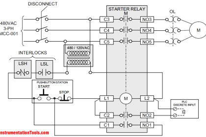
Let us understand the case first. A star delta starter has three electrical contactors – main, star, and delta. When the motor is started, the main contactor turns on and simultaneously, the star contactor turns on. Due to this, the motor is electrically connected to the star connection. The timer too starts when the star contactor turns on.

After 5 seconds, the delta contactor turns on and the star contactor turns off.  Due to this, the motor is electrically connected to the delta connection. The main contactor does not turn off; it turns off only when the motor is stopped. When the motor is stopped, all the three contactors remain off at the same time.

Now, we will write a PLC program for this. We will use Studio 5000 software and functional block diagram language. Following are the PLC inputs – start PB and stop PB. Following are the PLC outputs – main contactor, star contactor, and delta contactor. Refer to the below image for the logic written.
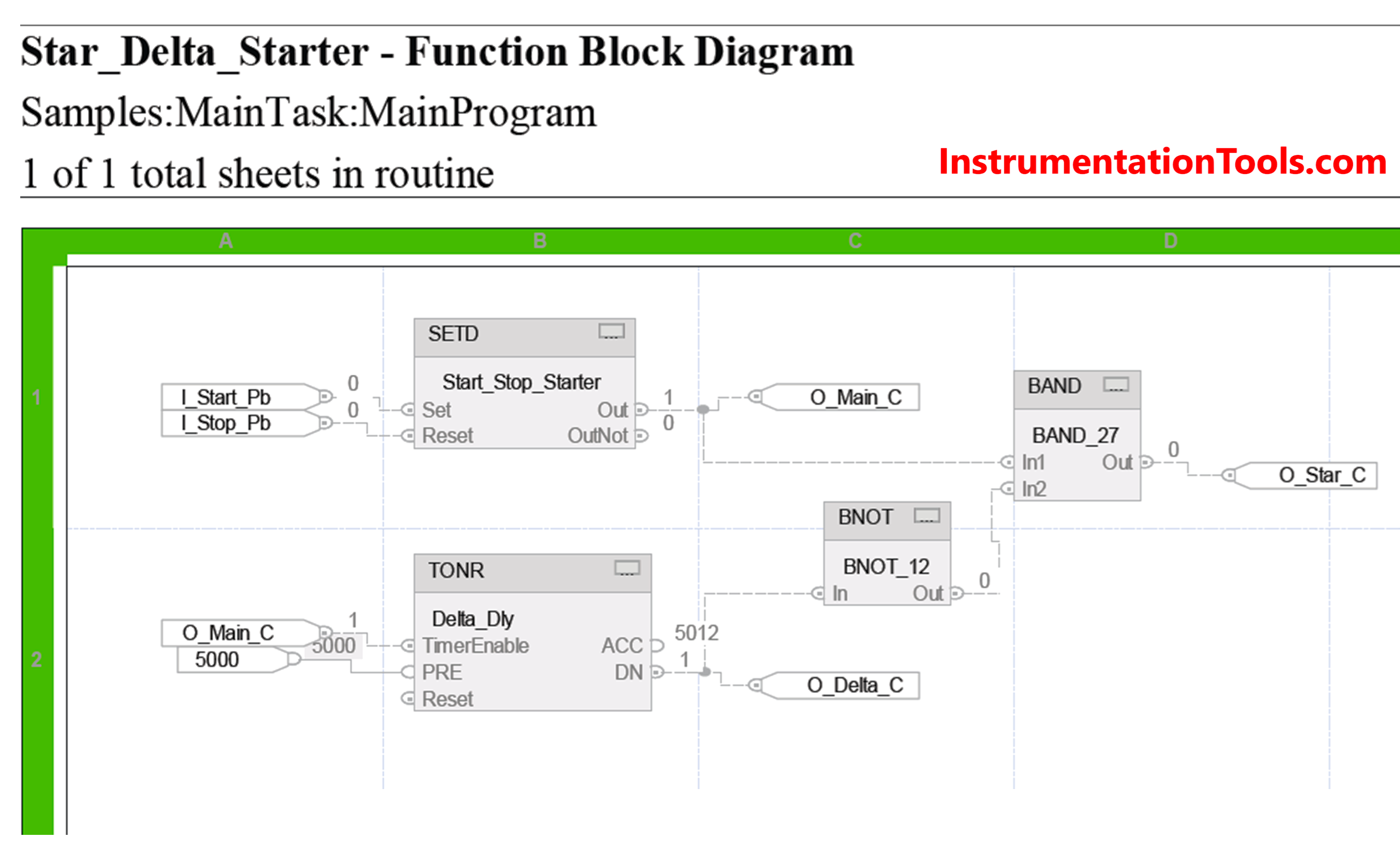
PLC Program for Star Delta Starter using Functional Block Diagram

Refer to the below image. We will first turn on the main contactor (shown in blue lines). We use the SETD block here. In this block, there are two inputs – set and reset. If the set bit is high, then the output is set. If the reset bit is high, then the output is reset, on the condition that the set input is not high.

It means set input is given priority over reset input. So, when the start button is pressed, the output turns on. When the stop button is pressed, the output turns off. All the outputs turn off as they all are linked with this single output.
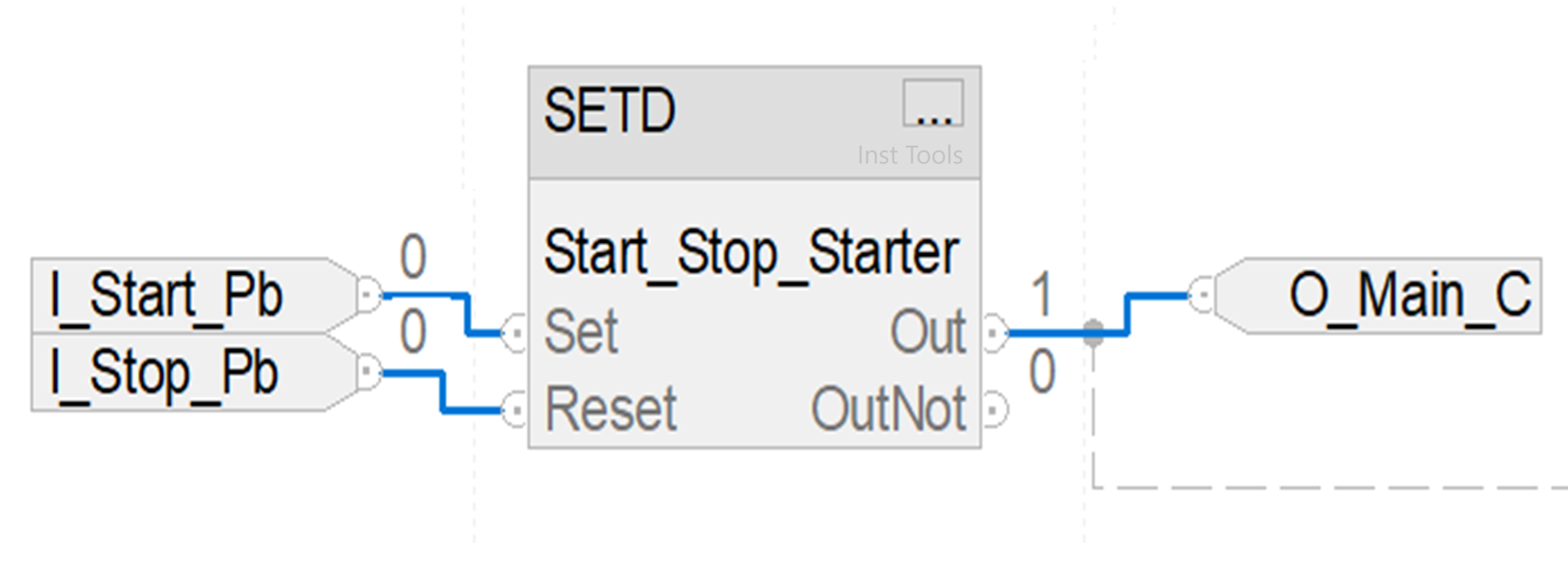
SETD block

Once the main contactor is on, we turn the star contactor on (shown in blue lines). Refer to the below image. It turns on when the main contactor is on and the timer of 5 seconds has not elapsed. Once the timer elapses, the output will turn off.
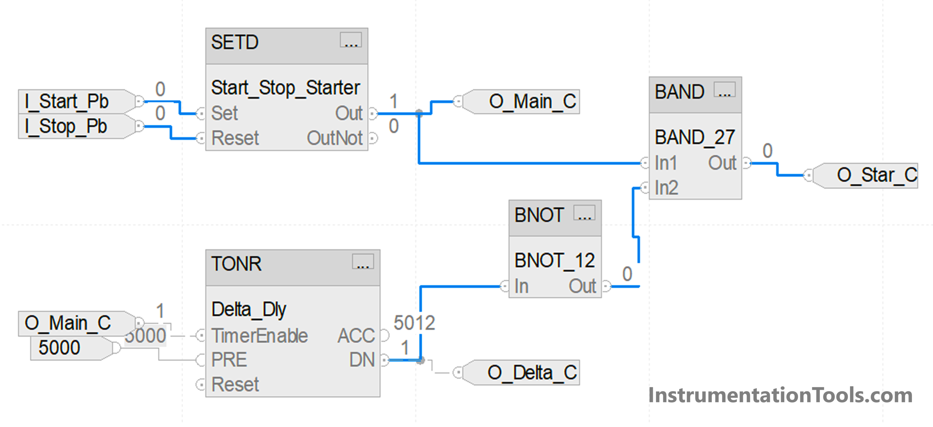
star delta starter function block

Once the main contactor is on, we also turn the timer on for the delta contactor (shown in blue lines). Refer to the below image. It turns on when the main contactor is on and the timer of 5 seconds has elapsed. Once the timer elapses, the output will turn on.
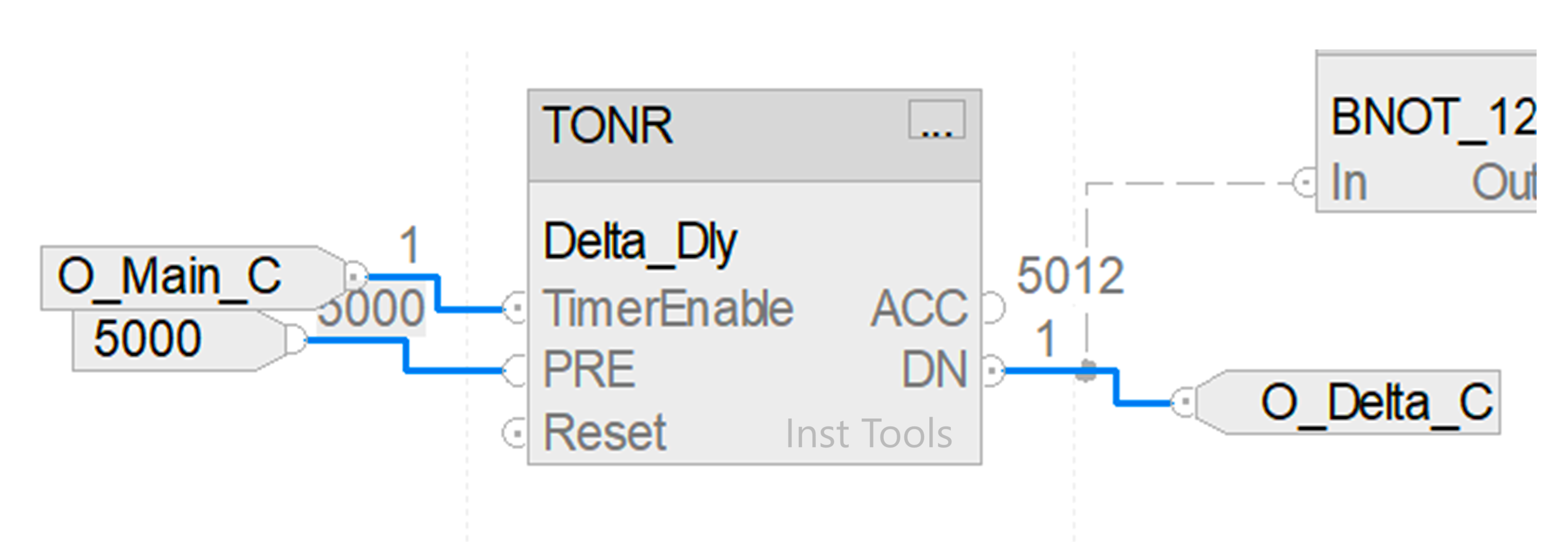
Function Block of Star Delta

In this way, we saw how to write a PLC program for star delta starters using a functional block diagram.

Read Next:

  • Star Delta Starter Circuit, Advantages, Disadvantages
  • Delta HMI and VFD Control with Modbus
  • Difference between Soft Starter and VFD
  • How to Run Multiple Motors with a Single VFD?
  • VFD Engineer Roles – Installation and Commissioning
Don't Miss Our Updates
Be the first to get exclusive content straight to your email.
We promise not to spam you. You can unsubscribe at any time.
Invalid email address
You've successfully subscribed !
Control Room and Field Instruments Questions and Answers
Draw a Ladder Logic to switch ON-OFF a Bulb using a Toggle Switch ?
How to Select a SCADA for New PLC Project?
Water Fountain Control Logic – PLC Exercises and Solutions
How to Choose a Suitable HMI for Your Application?
Share This Article
Facebook Whatsapp Whatsapp LinkedIn Copy Link
Share
Leave a Comment

Leave a Reply Cancel reply

Your email address will not be published. Required fields are marked *

Stay Connected

128.3kFollowersLike
69.1kFollowersFollow
208kSubscribersSubscribe
38kFollowersFollow

Categories

Recent Comments

  • Kamli on Top Free PLC Software
  • Guifty Shimica on Top Non-PLC Certification Courses for Automation Professionals
  • Guifty Shimica on Top Non-PLC Certification Courses for Automation Professionals
  • MIHARITSOA Aina Sitraka on Top Non-PLC Certification Courses for Automation Professionals

Related Articles

In this article, we will learn the difference between Machine Expert Basic and Machine Expert software in Schneider PLC.

Difference between Machine Expert Basic and Machine Expert – Schneider PLC

Schneider Electric Modicon M340 PAC

PLC vs PAC – Understanding the Key Differences and Similarities

Comparison of Proportional Integral Derivative Controllers (PID)

Comparison of Proportional Integral Derivative Controllers (PID)

Traces in TIA Portal

What is Trace Function in Tia Portal?

Ladder Diagram circuit

PLC Practice Questions

Add an alarm display to the graphics.

How to Configure an Alarm in InTouch SCADA?

STL Programming - SET, RESET, ASSIGN

STL Programming – SET, RESET, ASSIGN

Boolean Algebra to PLC Logic

From Boolean Algebra to PLC Logic

More Articles

Lime Slaker

Advancements in Lime Slaking Technology: What’s New And What’s Next

Aluminum CNC Machining Complete Guide

Aluminum CNC Machining: A Complete Guide You Cannot Miss

Chemical Reactor Vessel P and ID

Wrong Operation Internals Destroyed Demineralization Mixed Bed Vessel

Perfume filling system PLC program

CX Programmer Example: Perfume Mixing and Filling System

Omron PLC increment and decrement

Increment & Decrement Instructions in CX-Programmer (OMRON)

How to Link SQL With Indusoft Web Studio

How to Use an SQL Server with Indusoft Web Studio?

Magnetostrictive Transducers Objective Questions

Magnetostrictive Transducers Objective Questions

Electric Circuits Objective Questions

Electric Circuits Objective Questions – Set 6

Follow US
All rights reserved. Reproduction in whole or in part without written permission is prohibited.
Welcome Back!

Sign in to your account

Username or Email Address
Password

Lost your password?