In this article, you will learn the wood sawing and blower system automation and explained the PLC control design.
Note: This PLC logic is prepared for learning purposes and can be used to learn ladder logic programming.
Wood Sawing and Blower System
Problem Statement:
Design a PLC ladder logic for the following application.
We are using one Push Button and one sensor to control wood sawing and blower (fan).
The Sawing operation takes place for 10 seconds when the push button is pressed and the wood is placed there.
After the sawing operation is Complete, the wood is removed, and a blower (fan) is used to blow away the sawdust which remains activated for 5 seconds.
PLC Control Design
This video explains the PLC control programming with full details.
Inputs and Outputs
Digital Inputs:
Start Button: I0.0
Sensor: I0.1
Digital Outputs:
Saw: Q0.0
Fan: Q0.1
Ladder Logic
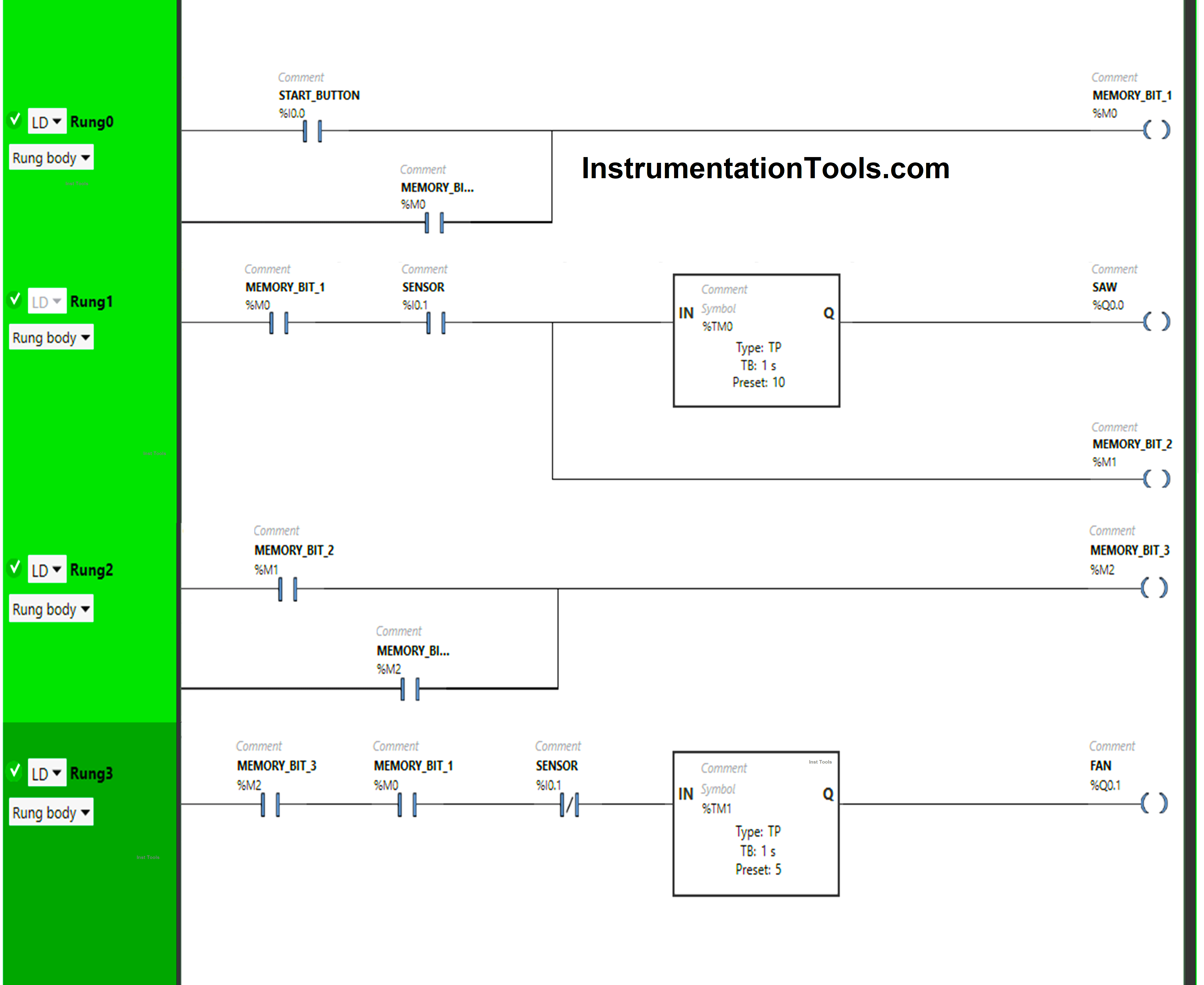
Program Explanation
We have used Normally Open Contacts for Start Button (I0.0), Sensor (I0.1), and Memory Bits.
We have used Normally Closed Contact for Sensor (I0.1)
In Rung 0:
- Normally Open Contact is used for the Start Button(I0.0) to Turn ON Memory Bit 1 (M0).
- Memory Bit 1 (M0) is latched so that when the Start Button (I0.0) turns OFF, Memory Bit 1 (M0) still remains ON.
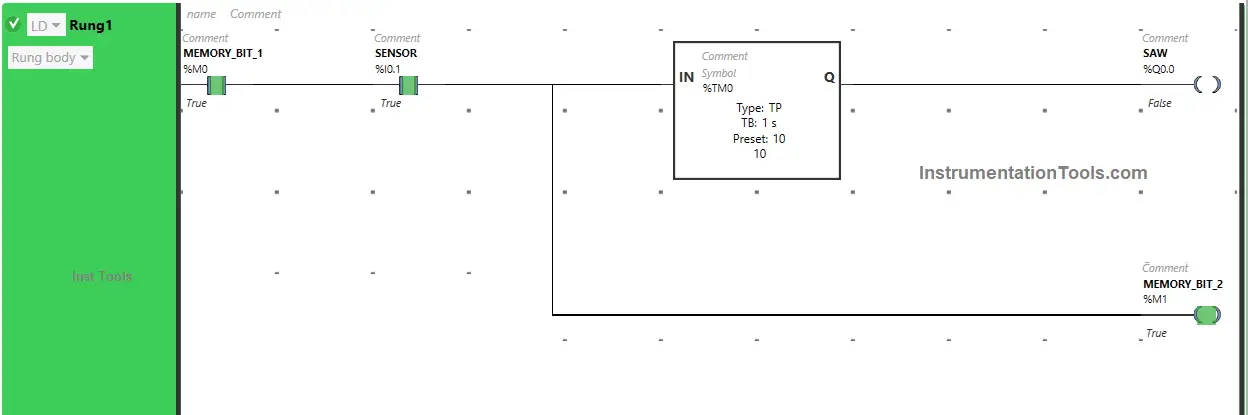
In Rung 1:
- Normally Open Contacts are used for Memory Bit 1 (M0) and Sensor (I0.1) to Turn ON the output Saw (I0.1) and Memory Bit 2 (M1).
- Timer Function Block type TP is used to Turn ON the output Saw (Q0.0) for a limited time.
In Rung 2:
- Normally Open Contact is used for Memory Bit 2 (M1) to Turn ON Memory Bit 3 (M2).
- Memory Bit 3 (M2) is latched so that Memory Bit 2 (M1) turns OFF, and Memory Bit 3 (M2) still remains ON.
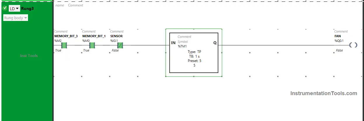
In Rung 3:
- Normally Open Contacts are used for Memory Bit 1 (M0) and Memory Bit 3 (M2) to turn ON the output Fan (Q0.1).
- Normally Closed Contact is used for the Sensor (I0.1) to Turn ON the output Fan (Q0.1).
- Timer Function Block type TP is used to Turn ON the output Fan (Q0.1) for a limited time.
Simulation Results
We simulate the PLC program and discuss the results. We show the partial logic in the test cases instead of the complete program. We recommend you to refer to the above video.
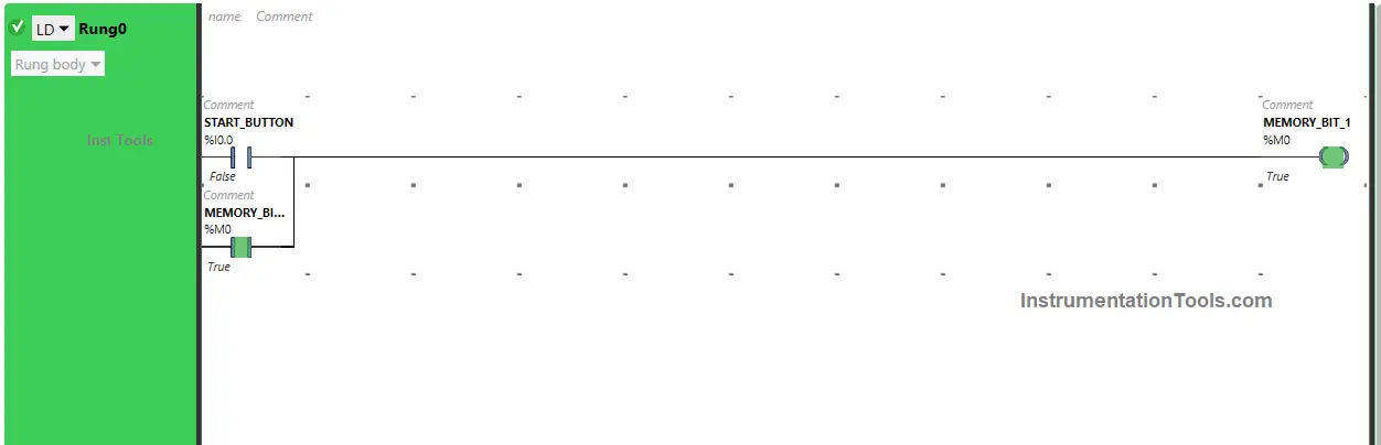
Rung 0 (When Start Button is Pressed):
When the Start Button (I0.0) is pressed and released, Memory Bit 1 (M0) turns ON and stores the data that the Start Button (I0.0) is pressed as Memory bits store the data.
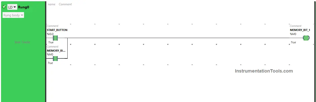
Memory Bit 1 (M0) is latched so that when the Start Button (I0.0) is released, Memory Bit 1 (M0) still remains ON.
Rung 1 (When Sensor gets Activated):
When Memory Bit 1 (M0) turns ON in Rung0, Normally Open Contact used for Memory Bit 1 (M0) in Rung1 will be in True State and will pass the signal to pass through it.
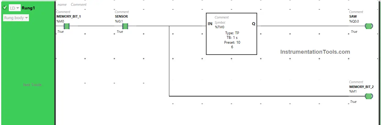
When Sensor (I0.1) gets activated (Sensor detects wood), the output Saw (Q0.0) turns ON (Sawing Operation starts), and Memory Bit 2 (M1) turns ON.
The output Saw (Q0.0) will turn OFF after some time as Timer Function Type TP is used to turn ON the output Saw (Q0.0) for a limited time. The time is set to 10 seconds.
After 10 seconds, the output Saw (Q0.0) turns OFF (Sawing operation finishes).
Rung 2:
When Memory Bit 2 (M1) turns ON in Rung1, Normally Open Contact used for Memory Bit 2 (M1) in Rung2 will be in True State and will pass the signal to turn ON Memory Bit 3 (M2).

Memory Bit 3 (M2) is latched so that when Memory Bit 2 (M1) turns OFF, Memory Bit 3 (M2) still remains ON.
Rung 3 (When Sensor gets deactivated):
When Memory Bit 1 (M0) turns ON in Rung0 and Memory Bit 3 (M2) turns ON in Rung2, Normally Open Contacts used for Memory Bit 1 (M0) and Memory Bit 3 (M2) in Rung3 will be in True State, and will pass the signal to pass through it.
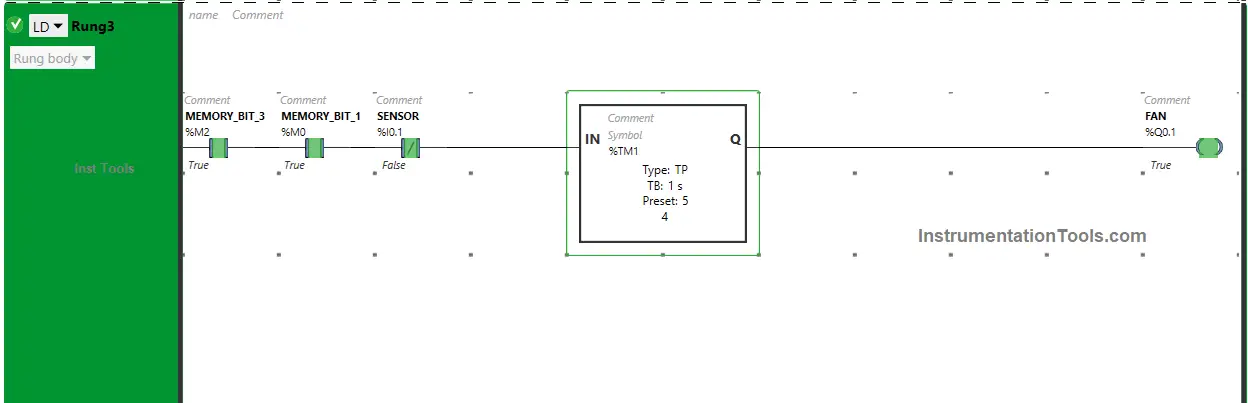
When Sensor (I0.1) gets deactivated (Sensor does not detect wood or Wood is removed after Sawing Operation), the output Fan (Q0.1) turns ON ( Fan starts)as Normally Closed Contact used for Sensor (I0.1) will be in False state and passes the signal to turn ON the output Fan (Q0.1) and the output Fan (Q0.1) turns ON.
The output Fan (Q0.1) will turn OFF after some time as Timer Function Type TP is used to turn ON the output Fan (Q0.1) for a limited time. The time is set to 5 seconds. After 5 seconds, the output Fan (Q0.1) turns OFF (Fan stops).
If you liked this article, please subscribe to our YouTube Channel for PLC and SCADA video tutorials.
You can also follow us on Facebook and Twitter to receive daily updates.
Read Next:
- Ladder Logic Program for Push Button and Motor
- Conveyor Operation with a Backup Motor using PLC
- PLC Program for Gas Pressure Closed-Loop Control
- Electrical Machines Objective Questions and Answers
- Industrial Drives Objective Questions and Answers