Inst ToolsInst ToolsInst Tools
  • Courses
  • Automation
    • PLC
    • Control System
    • Safety System
    • Communication
    • Fire & Gas System
  • Instrumentation
    • Design
    • Pressure
    • Temperature
    • Flow
    • Level
    • Vibration
    • Analyzer
    • Control Valve
    • Switch
    • Calibration
    • Erection & Commissioning
  • Interview
    • Instrumentation
    • Electrical
    • Electronics
    • Practical
  • Q&A
    • Instrumentation
    • Control System
    • Electrical
    • Electronics
    • Analog Electronics
    • Digital Electronics
    • Power Electronics
    • Microprocessor
  • Request
Search
  • Books
  • Software
  • Projects
  • Process
  • Tools
  • Basics
  • Formula
  • Power Plant
  • Root Cause Analysis
  • Electrical Basics
  • Animation
  • Standards
  • 4-20 mA Course
  • Siemens PLC Course
Reading: 4-20mA Graphical Calculations
Share
Font ResizerAa
Inst ToolsInst Tools
Font ResizerAa
  • Courses
  • Design
  • PLC
  • Interview
  • Control System
Search
  • Courses
  • Automation
    • PLC
    • Control System
    • Safety System
    • Communication
    • Fire & Gas System
  • Instrumentation
    • Design
    • Pressure
    • Temperature
    • Flow
    • Level
    • Vibration
    • Analyzer
    • Control Valve
    • Switch
    • Calibration
    • Erection & Commissioning
  • Interview
    • Instrumentation
    • Electrical
    • Electronics
    • Practical
  • Q&A
    • Instrumentation
    • Control System
    • Electrical
    • Electronics
    • Analog Electronics
    • Digital Electronics
    • Power Electronics
    • Microprocessor
  • Request
Follow US
All rights reserved. Reproduction in whole or in part without written permission is prohibited.
Inst Tools > Blog > Formulas > 4-20mA Graphical Calculations

4-20mA Graphical Calculations

Last updated: March 27, 2023 9:54 am
Editorial Staff
Formulas
3 Comments
Share
3 Min Read
SHARE

An illustration sometimes find helpful in understanding analog signal ranges is to consider the signal range as a length expressed on a number line.

4-20mA Graphical Calculations

For example, the common 4-20 mA analog current signal range would appear as such:

4-20mA Graph

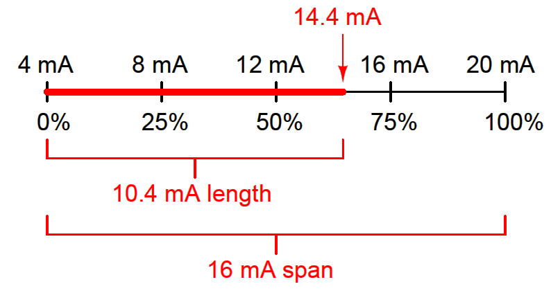
If one were to ask the percentage corresponding to a 14.4 mA signal on a 4-20 mA range, it would be as simple as determining the length of a line segment stretching from the 4 mA mark to the 14.4 mA mark:
4-20mA Image

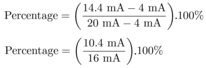
As a percentage, this thick line is 10.4 mA long (the distance between 14.4 mA and 4 mA) over a total (possible) length of 16 mA (the total span between 20 mA and 4 mA). Thus:
4-20mA to Percentage Calculation

Percentage = 65%

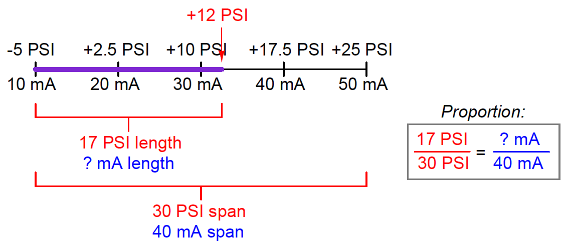
This same “number line” approach may be used to visualize any conversion from one analog scale to another. Consider the case of an electronic pressure transmitter calibrated to a pressure range of −5 to +25 PSI, having an (obsolete) current signal output range of 10 to 50 mA.

The appropriate current signal value for an applied pressure of +12 PSI would be represented on the number line as such:
3-15psi to 4-20mA conversion

Finding the “length” of this line segment in units of milliamps is as simple as setting up a proportion between the length of the line in units of PSI over the total (span) in PSI, to the length of the line in units of mA over the total (span) in mA:

Solving for the unknown (?) current by cross-multiplication and division yields a value of 22.67 mA.

Of course, this value of 22.67 mA only tells us the length of the line segment on the number line; it does not directly tell us the current signal value.

To find that, we must add the “live zero” offset of 10 mA, for a final result of 32.67 mA.
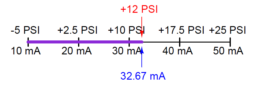
Calculate 4-20mA Equivalent

Thus, an applied pressure of +12 PSI to this transmitter should result in a 32.67 mA output signal.

4-20 mA into 0-100 % Calculation Formula - Instrumentation Tutorials

Read Next:

  • History of 3-15 psi & 4-20 mA
  • 4-20mA Conversions Easily
  • Zero and Span Calibration
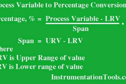
  • Process Variable Conversion
  • Calculate Temperature Transmitter
Don't Miss Our Updates
Be the first to get exclusive content straight to your email.
We promise not to spam you. You can unsubscribe at any time.
Invalid email address
You've successfully subscribed !

Continue Reading

Formula to Calculate Process Variable from 4-20mA
PLC Analog Input Conversion Formula
DP Transmitter Dry Leg & Wet Leg Calculations
Calculate Flow Transmitter Output Current
Calculate Process Variable from Transmitter Current
Calculate Temperature Coefficient of RTD
Share This Article
Facebook Whatsapp Whatsapp LinkedIn Copy Link
Share
3 Comments
  • Nayan Gohil says:
    August 7, 2016 at 1:54 am

    Thanks for the info.

    Reply
  • giddaiah says:
    August 7, 2016 at 4:34 pm

    very nice useful for all our inst dept shadnagar hyd

    Reply
  • mputu kabutoto says:
    October 14, 2021 at 9:12 pm

    l like this courso for me can you send this courso for my email

    Reply

Leave a Reply Cancel reply

Your email address will not be published. Required fields are marked *

Stay Connected

128.3kFollowersLike
69.1kFollowersFollow
210kSubscribersSubscribe
38kFollowersFollow

Categories

Explore More

Example of 3-15 psi to 4-20mA Conversion
Calculate Temperature Transmitter Output
Transmitter Turndown Ratio, Set Span and Zero Span
Remote Seal Transmitters Ranging Calculation
Linear to Square Root Extraction
Formula to Calculate 3-15psi from 4-20mA Current
Formula for Percentage to Process Variable Conversion
How to do 4-20mA Conversions Easily

Keep Learning

Control Valve Cv Formula

Control Valve Cv calculation

Control valve positioner calculation

Calculate Control Valve Stem Position

Level Calculation with Remote Seals

Level Calculation with Remote Seals

Zero Suppression in level Measurement

Zero Suppression and Zero Elevation Calculations

Closed Tank Level Measurement Formula

Siemens Differential Pressure Transmitter Calculations (Flange Type)

Relationship between Temperature Scales

Relationship between Temperature Scales

Process-Variable-to-Percentage-Conversion

Formula for Process Variable to Percentage Conversion

PLC Problems Troubleshooting

PLC Problems Troubleshooting

Learn More

Types of Boiler Drought

What is a Boiler Draught System? – Purpose, Types, Advantages

High-pressure Service Level Transmitters Misunderstood Zero Drifts

High-pressure Service Level Transmitters Misunderstood Zero Drifts

PLC Memory Mapping

PLC Memory Mapping and I/O addressing

Transistor Failure Rate Calculation

Transistor Failure Rate Calculation

Structured Control Language (SCL) Elements

Value Assignments in SCL Language – Single, Multiple, Combined

Batch Pan Automation in the sugar industry

Batch Pan Automation in the Sugar Industry

Anti Surge Controller Theory

Anti Surge Controller Working Principle

What is Ground

What is Ground, and importance of a Grounding System?

Menu

  • About
  • Privacy Policy
  • Copyright

Quick Links

  • Learn PLC
  • Helping Hand
  • Part Time Job

YouTube Subscribe

Follow US
All rights reserved. Reproduction in whole or in part without written permission is prohibited.
Welcome Back!

Sign in to your account

Username or Email Address
Password

Lost your password?