This article talks about the simple exhaust fan control logic using the PLC timers.
Note: This example program is for education purposes and for practicing PLC programming.
Exhaust Fan Control
Problem Statement:
Design a PLC ladder logic for the following application.
We are using one toggle switch to control the Stove and Exhaust Fan.
When the Stove is turned ON, the exhaust fan will be turned ON and it remains ON for 1 minute after the Stove is turned OFF.
eLearning PLC Training Courses
Inst Tools provides free eLearning PLC training courses for engineering students to learn about programmable logic controllers.
Inputs/Outputs
Digital Inputs:
Start Button: I0.0
Digital Outputs:
Stove: Q0.0
Exhaust Fan: Q0.1
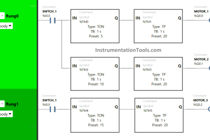
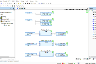
Example of PLC Timer Programming
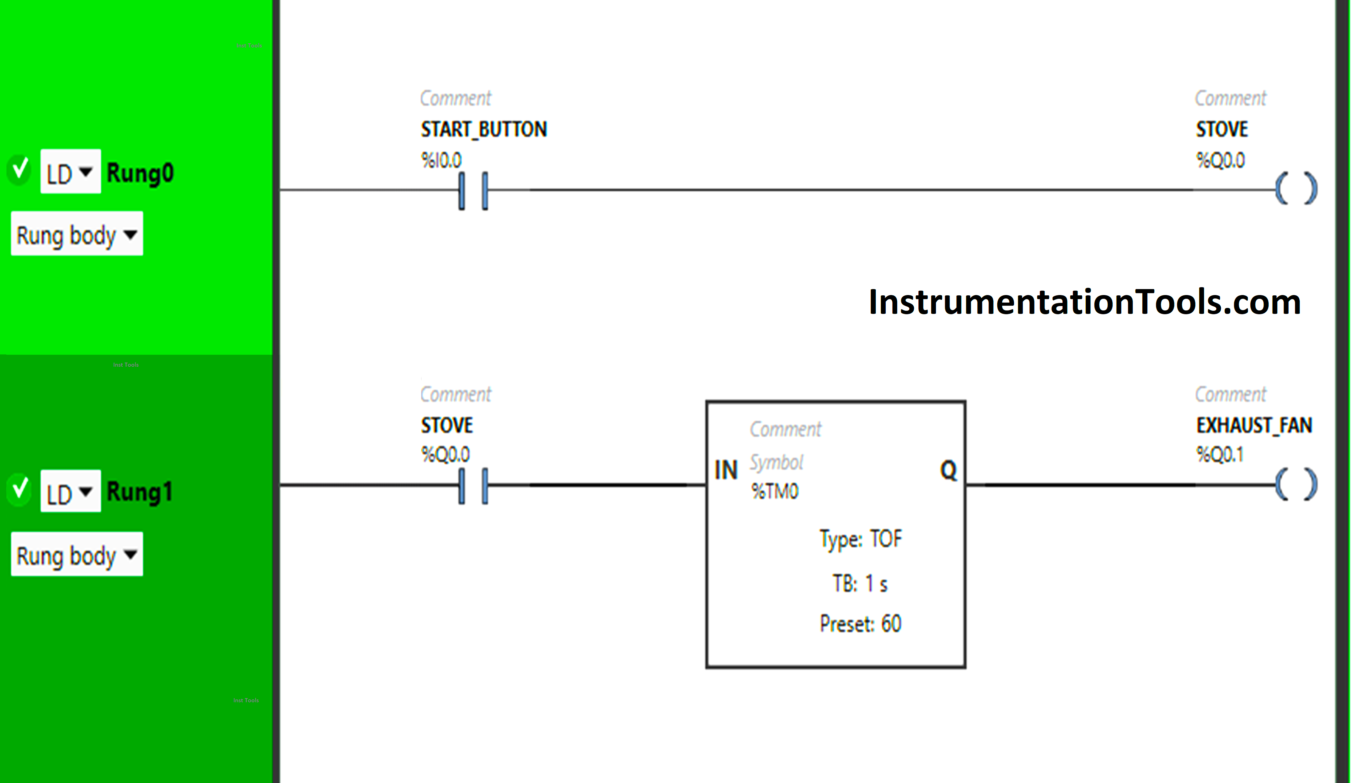
Explanation of Program
We have used Normally Open Contact for the Start Button (I0.0) and Stove (Q0.0).
In Rung 0:
- Normally Open Contact is used for the Start Button (I0.0) to Turn ON the output Stove(Q0.0).
In Rung 1:
- Normally Open Contact is used for the Stove (Q0.0) to Turn ON the output Exhaust Fan (Q0.1).
- TOF timer is used to delay the turning OFF time of the output Exhaust Fan (Q0.1) for some time.
So, When the Start Button (I0.0) is turned ON, the output Stove (Q0.0) will turn ON as Normally Open Contact used for the Start Button (I0.0) will be in True State and will pass the signal to the output Stove (Q0.0) and the output stove (Q0.0) will turn ON.
When the output Stove (Q0.0) turns ON in Rung0, Normally Open Contact used for the Stove in Rung1 will be in True State and allow the signal to flow through it and the output (Q0.1) Exhaust Fan will turn ON.
The output Stove (Q0.0) will turn OFF when the Start Button (I0.0) is turned OFF as Normally Open Contact used for the Start Button (I0.0) will be in a false state and does not allow the signal to flow through it.
When the output Stove (Q0.0) is turned OFF in Rung0, Normally Open Contact used for the Stove in Rung1 will be in a False State and will not pass the signal to the output Exhaust Fan (Q0.1).
The output Exhaust Fan (Q0.0) will turn OFF but after 60 seconds as the Timer Function Block type TOF is used to delay the turning OFF time of the output Exhaust Fan (Q0.1).
The time is set to 60 seconds. So when the output Stove (Q0.0) turns OFF after 60 seconds the output Exhaust Fan (Q0.1) will turn OFF.
Simulation
Let’s simulate our logic and see the results.
When the Start Button (I0.0) is turned ON
In Rung0, When the Start Button (I0.0) is turned ON, the output Stove (Q0.0) will turn ON as Normally Open Contact used for the Start Button (I0.0) will be in True State and will pass the signal to the output Stove (Q0.0) and the output stove (Q0.0) will turn ON.
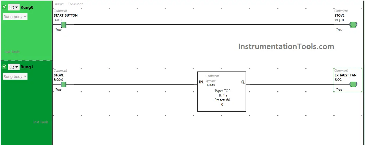
When the output Stove (Q0.0) turns ON in Rung0, Normally Open Contact used for the Stove in Rung1 will be in True State and allow the signal to flow through it and the output (Q0.1) Exhaust Fan will turn ON.
When the Start Button (I0.0) is turned OFF
The output Stove (Q0.0) will turn OFF when the Start Button (I0.0) is turned OFF as Normally Open Contact used for the Start Button (I0.0) will be in a false state and does not allow the signal to flow through it.
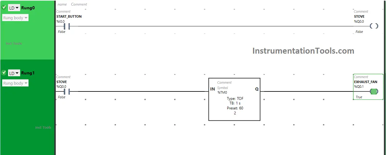
When the output Stove (Q0.0) is turned OFF in Rung0, Normally Open Contact used for the Stove in Rung1 will be in a False State and will not pass the signal to the output Exhaust Fan (Q0.1).
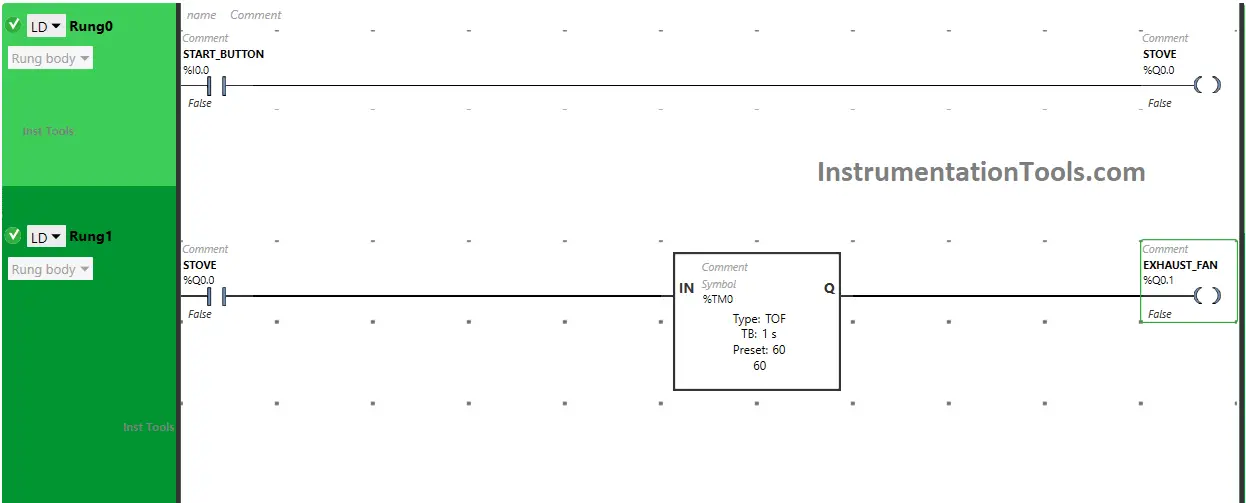
The output Exhaust Fan (Q0.0) will turn OFF but after 60 seconds as the Timer Function Block type TOF is used to delay the turning OFF time of the output Exhaust Fan (Q0.1). The time is set to 60 seconds. So when the output Stove (Q0.0) turns OFF after 60 seconds the output Exhaust Fan (Q0.1) will turn OFF.
If you liked this article, please subscribe to our YouTube Channel for PLC and SCADA video tutorials.
You can also follow us on Facebook and Twitter to receive daily updates.
Read Next:
- PLC Programming to Control a Pump
- Manufacturing Line Assembly PLC Logic
- PLC Ladder Logic Classroom Bell System
- Batch Mixing PLC Ladder Logic Program
- PLC Pushbutton and Motor Ladder Logic


(%Q0.0) NC contact is false when toggle switch is off. how come the logic flow is maintained through timer to exhaust output(%Q0.1).