Inst ToolsInst ToolsInst Tools
  • Courses
  • Automation
    • PLC
    • Control System
    • Safety System
    • Communication
    • Fire & Gas System
  • Instrumentation
    • Design
    • Pressure
    • Temperature
    • Flow
    • Level
    • Vibration
    • Analyzer
    • Control Valve
    • Switch
    • Calibration
    • Erection & Commissioning
  • Interview
    • Instrumentation
    • Electrical
    • Electronics
    • Practical
  • Q&A
    • Instrumentation
    • Control System
    • Electrical
    • Electronics
    • Analog Electronics
    • Digital Electronics
    • Power Electronics
    • Microprocessor
  • Request
Search
  • Books
  • Software
  • Projects
  • Process
  • Tools
  • Basics
  • Formula
  • Power Plant
  • Root Cause Analysis
  • Electrical Basics
  • Animation
  • Standards
  • 4-20 mA Course
  • Siemens PLC Course
Reading: PLC Code to Start & Stop Motor and Pump as per Logic
Share
Font ResizerAa
Inst ToolsInst Tools
Font ResizerAa
  • Courses
  • Design
  • PLC
  • Interview
  • Control System
Search
  • Courses
  • Automation
    • PLC
    • Control System
    • Safety System
    • Communication
    • Fire & Gas System
  • Instrumentation
    • Design
    • Pressure
    • Temperature
    • Flow
    • Level
    • Vibration
    • Analyzer
    • Control Valve
    • Switch
    • Calibration
    • Erection & Commissioning
  • Interview
    • Instrumentation
    • Electrical
    • Electronics
    • Practical
  • Q&A
    • Instrumentation
    • Control System
    • Electrical
    • Electronics
    • Analog Electronics
    • Digital Electronics
    • Power Electronics
    • Microprocessor
  • Request
Follow US
All rights reserved. Reproduction in whole or in part without written permission is prohibited.
Inst Tools > Blog > PLC Tutorials > PLC Code to Start & Stop Motor and Pump as per Logic

PLC Code to Start & Stop Motor and Pump as per Logic

In this article, you will learn the PLC code to start & stop motor and pump as per logic and understand the programming basics.

Last updated: April 8, 2024 1:24 pm
Editorial Staff
PLC Tutorials
No Comments
Share
7 Min Read
SHARE

In this article, you will learn the PLC code to start & stop motor and pump as per logic and understand the programming basics.

Contents
PLC CodeHands-On PLC VideosInputsOutputsStart & Stop the Motor and Pump LogicPLC Logic DescriptionTest Results Overview

Note: The PLC code example is prepared to understand the basic programming for beginners.

PLC Code

Problem Statement

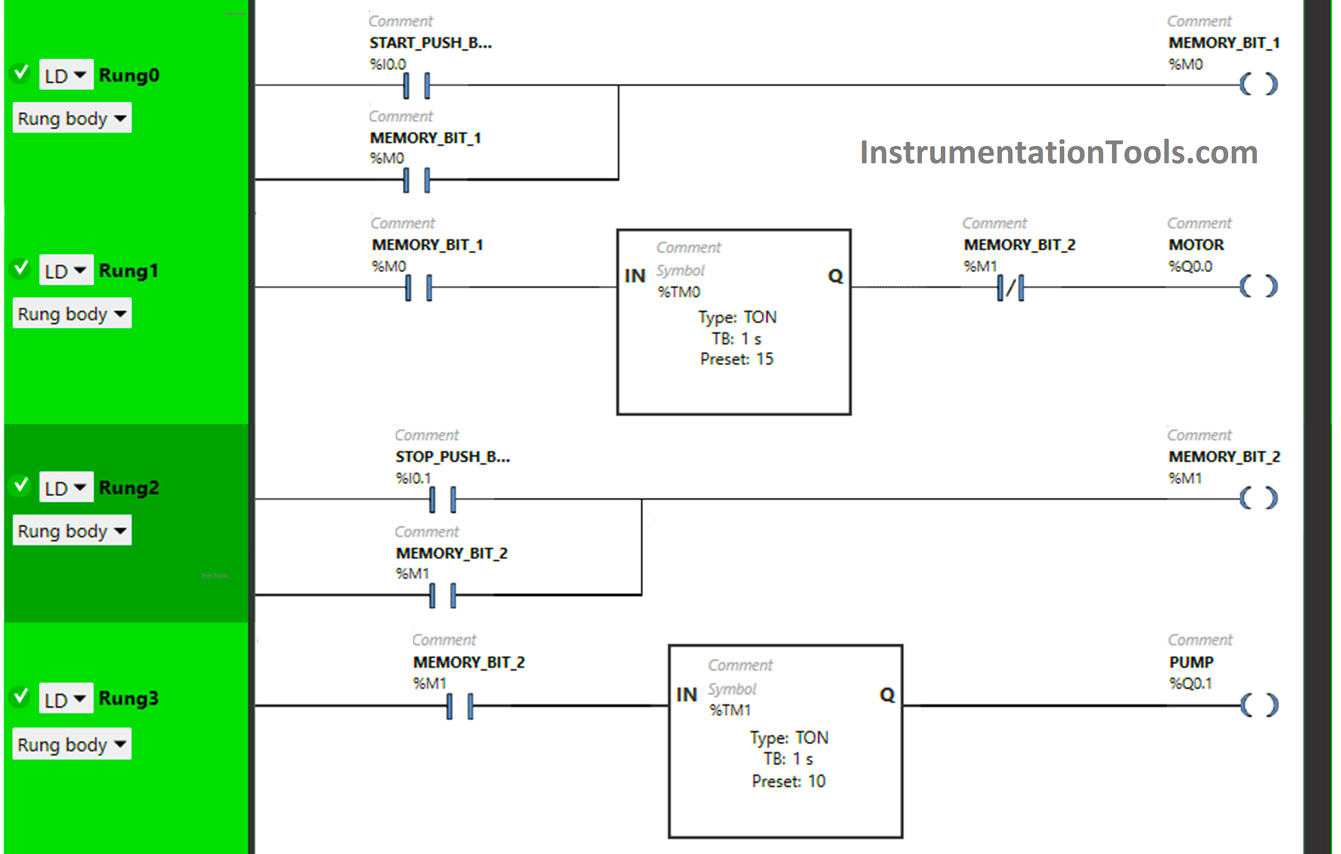
Design a PLC ladder logic for the following application.

We are using two Push Buttons to control a Motor and Pump.

When the Start Push Button is pressed and released, the Motor will be ON after 15 seconds.

When the Stop Push Button is pressed and released, the Motor will stop immediately and the Pump will Turn ON after 10 seconds.

Hands-On PLC Videos

Try our PLC programming videos to understand the example problems and practice them to get hands-on experience with the software.

PLC Code - START STOP Motor & Pump - Learn Schneider PLC

Inputs

Digital Inputs

Start Push Button: I0.0

Stop Push Button: I0.1

Outputs

Digital Outputs

Motor: Q0.0

Pump: Q0.1

Start & Stop the Motor and Pump Logic
PLC Code to Start & Stop Motor and Pump as per Logic

PLC Logic Description

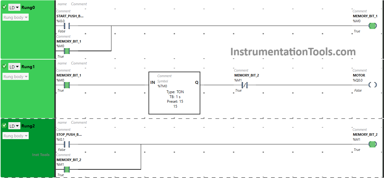
Here we used Normally Open Contact for the Start Push Button, Stop Push Button, and Memory Bits.

Normally Closed Contact is used for Memory Bit 2 in Rung1.

Two Timer Function Block Type TON is used for the Motor and Pump.

In Rung 0:

  • Normally Open Contact is used for the Start Push Button to Turn ON Memory Bit 1.
  • Latching is used for Memory Bit 1 so that when the Start Push Button is released, Memory Bit 1 still remains ON.

In Rung 1:

  • Normally Open Contact is used for Memory Bit 1 to Turn ON Motor.
  • Normally Closed Contact is used for Memory Bit 2 to Turn OFF Motor.
  • Timer Function Block type TON is used for the Motor to delay the Turning ON time.

In Rung 2:

  • Normally Open Contact is used for Stop Push Button to Turn ON Memory Bit 2.
  • Latching is used for Memory Bit 2 so that when the Stop Push Button is released, Memory Bit 2 still remains ON.

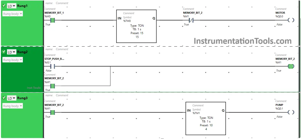
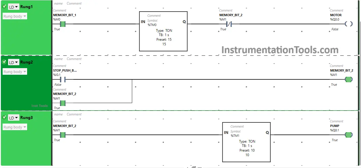
In Rung 3:

  • Normally Open Contact is used for Memory Bit 2 to Turn ON Pump.
  • Timer Function Block type TON is used for the Pump to delay the Turning ON time.

When the Start Push Button is pressed and released, Memory Bit 1 Turns ON in Rung0 and Rung1. when Memory Bit 1 Turns ON in Rung1, the Timer starts in Timer Function Block type TON which is set to 15 seconds and then, it delays 15 seconds to Turn ON the Motor. In a false state, Normally Closed Contact used for Memory Bit 2 also Passes the signal and the Motor will Turn ON after 15 seconds.

When the Stop Push Button is pressed and released, Memory Bit 2 will Turn ON in Rung1, Rung2, and Rung3 as Normally Open Contact is used for the Stop Push Button that allows the signal to pass and Turn ON Memory Bit 2.

When Memory Bit 2 Turns ON, the Motor will Turn OFF immediately because Normally Closed Contact used for Memory Bit 2 in Rungs1 will be in a True state and will not pass the signal to the Motor.

As Memory Bit 2 turns ON in Rung3,  Timer starts in Timer Function Block type TON which is set to 10 seconds and then, it delays 10 seconds to Turn ON the Pump and the Pump will Turn ON after 15 seconds.

Test Results Overview

Check the below program test results.

When Start Push Button is Pressed and Released
Motors Start Easy PLC Programming

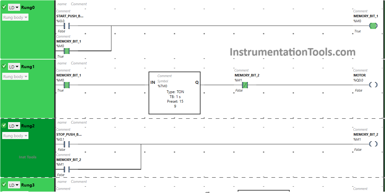
When the Start Push Button is pressed and released, Memory Bit 1 Turns ON in Rung0 and Rung1 as Normally Open Contact is used for the Start Push Button that allows the signal to pass and Turn ON Memory Bit 1.

start stop motor control ladder diagram

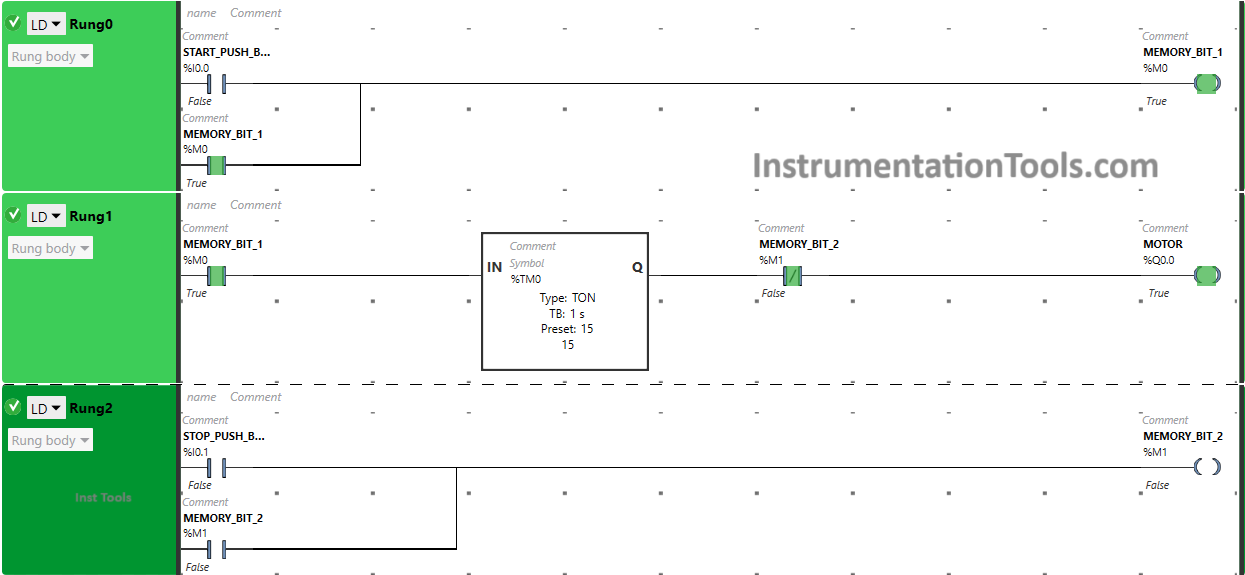
When Memory Bit 1 Turns ON in Rung1, the signal flows through it because Normally Open Contact is used for it and the Timer starts in the Timer Function Block type TON Which delays the time to Turn ON the Motor.

In this Timer Function Block, time is set to 15 seconds. In a false state, Normally Closed Contact used for Memory Bit 2 also Passes the signal and the Motor will Turn ON after 15 seconds.

When Stop Push Button is Pressed and Released

When the Stop Push Button is pressed and released, Memory Bit 2 will Turn ON in Rung1, Rung2, and Rung3 as Normally Open Contact is used for the Stop Push Button that allows the signal to pass and Turn ON Memory Bit 2.
Motor and Pump as per Logic

When Memory Bit 2 Turns ON, the Motor will Turn OFF immediately because Normally Closed Contact used for Memory Bit 2 in Rung1 will be in a True state and will not pass the signal to the Motor.
PLC Controls with Ladder Diagram

As Memory Bit 2 turns ON in Rung3, the Pump will Turn ON after 10 seconds because Timer Function Block type TON is used for the Pump which delays the time of the Pump to Turn ON.
Electrical Controls Motor

If you liked this article, please subscribe to our YouTube Channel for PLC and SCADA video tutorials.

You can also follow us on Facebook and Twitter to receive daily updates.

Read Next:

  • PLC Automatic Control of Two Outputs
  • From Boolean Algebra to PLC Logic
  • PLC Program for Solenoid & Pilot Lamp
  • PLC Programming Example with Motor
  • PLC to Start or Stop using 1 Switch Program
Don't Miss Our Updates
Be the first to get exclusive content straight to your email.
We promise not to spam you. You can unsubscribe at any time.
Invalid email address
You've successfully subscribed !

Continue Reading

Tools Required for PLC Programmer to Carry at Site
Troubleshooting a 4-20mA Current loop
How to Prevent Ground Loops in Analog Circuits?
How to Troubleshoot a PLC System?
Configuration of Input and Output Tags in Siemens Scada and PLC
PLC Programming to Control Lights in a Sequence
Share This Article
Facebook Whatsapp Whatsapp LinkedIn Copy Link
Share
Leave a Comment

Leave a Reply Cancel reply

Your email address will not be published. Required fields are marked *

Stay Connected

128.3kFollowersLike
69.1kFollowersFollow
210kSubscribersSubscribe
38kFollowersFollow

Categories

Explore More

PLC Simulator using Excel
Motor Starter Logic using Siemens PLC Tia Portal
Problem on PLC, HMI, VFD, and Motor Circuit
Coil Type Timers in Siemens PLC Programming
PLC vs PAC – Understanding the Key Differences and Similarities
How to implement SR Flip Flop using PLC Ladder Logic
Flood Warning System using Programmable Logic Controller
What is Interposing Relay in a PLC System ?

Keep Learning

Pneumatic valve operation in sequence mode

Sequential PLC Programming for the Pneumatic Valves

Types of Limit Switches

Types of Limit Switches – Principle, Advantages, Disadvantages

Reset Logic for pump Run Hours

PLC Program to Count Running Hours of any Equipment

Omron PLC programs

Daily Alarm PLC Program using Real-Time Clock

Motor Stop Interlock for Changing the Direction PLC Program

Motor Stop Interlock for Changing the Direction PLC Program

PLC Program for Sequential Motor Control

PLC Program for Sequential Motor Control

Structured Text PLC Example for Motor Interlocking and Control

Structured Text PLC Example for Motor Interlocking and Control

traffic light plc program

Traffic Light Control using PLC Ladder Logic

Learn More

Drum water level control

Closed Loop Control System : Boiler Water Level Control System

Basics of PID Controllers

PID Controllers in Closed Loop Control Systems – PLC Basics

PLC Program using Counters

PLC Counters Program

ANSI Class Relates to PSI

How ANSI Class Relates to PSI ?

PID Setup

PID in Studio 5000

Electrical Machines Questions and Answers

Double Excited Magnetic System Quiz

Digital Control Systems

Compensation Techniques : Control Systems

Example of PLC Programming based on Logic Circuit

Example of PLC Programming based on Logic Circuit

Menu

  • About
  • Privacy Policy
  • Copyright

Quick Links

  • Learn PLC
  • Helping Hand
  • Part Time Job

YouTube Subscribe

Follow US
All rights reserved. Reproduction in whole or in part without written permission is prohibited.
Welcome Back!

Sign in to your account

Username or Email Address
Password

Lost your password?