Both magnetic flowmeters and turbine flowmeters are used for measuring the flow rate of fluids in various industries, including chemical, petrochemical, water treatment, and food processing plants.
Though they have a common application, their underlying principles and operational characteristics differ significantly.
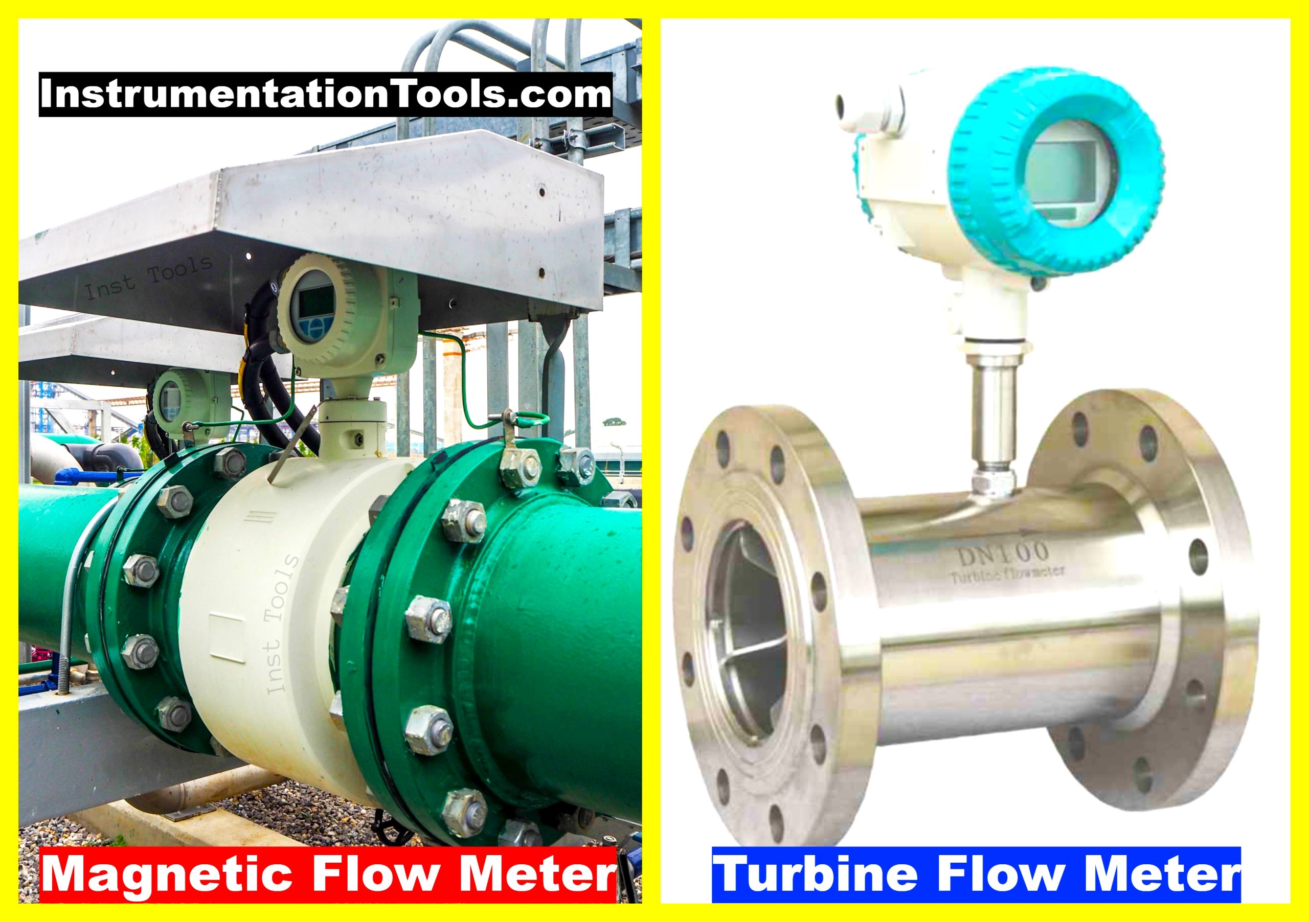
Magnetic Flowmeter vs. Turbine Flowmeter
Here is a detailed comparison between Magnetic Flowmeters and Turbine Flowmeters in the below table.
| S.No. | Comparison Factor | Magnetic Flowmeter | Turbine Flowmeter |
|---|---|---|---|
| 1 | Working Principle | Operates on Faraday’s Law of Electromagnetic Induction. Voltage is generated when a conductive fluid flows through a magnetic field, and this voltage is used to measure flow rate. | Operates mechanically. Fluid flows through and rotates a turbine. The rotational speed is measured by an optical or magnetic sensor and is proportional to the fluid’s velocity. |
| 2 | Conductivity Requirements | Requires fluid to be conductive. Not suitable for non-conductive fluids like oils and gases. | No conductivity requirements. Can measure both conductive and non-conductive fluids. |
| 3 | Installation and Orientation | Flexible in installation orientation due to absence of moving parts. | Requires specific orientation to ensure free rotation of the turbine, affecting measurement accuracy. |
| 4 | Pressure Drop | Minimal to no pressure drop as there are no mechanical obstructions. | May experience some pressure drop due to the presence of the turbine in the fluid path. |
| 5 | Accuracy and Sensitivity | High accuracy for conductive fluids. Less sensitive to variations in fluid properties. | Can be very accurate but sensitive to variations like fluid viscosity, requiring more frequent calibration. |
| 6 | Wear and Tear | Minimal wear and tear due to the absence of moving parts. | Moving parts like turbine blades can wear out, especially when used with abrasive or corrosive fluids. |
| 7 | Application Suitability | Ideal for wastewater treatment, slurries, and other applications requiring conductive fluids. | Suitable for measuring clean, non-corrosive fluids including oils and gases. |
| 8 | Cost | Generally more expensive due to the complexity of electromagnetic technology. | Less expensive initially but may have additional costs for maintenance and calibration. |
| 9 | Calibration | Requirements Usually calibrated at the factory and requires less frequent field calibration. | Fluid properties have minimal impact on accuracy. Requires more frequent field calibration due to sensitivity to fluid properties like viscosity. |
| 10 | Maintenance | Low maintenance requirements due to the absence of moving mechanical parts. | Higher maintenance needs, especially for calibrations and possible part replacements. |
| 11 | Response Time | Generally offers rapid response time because of electronic measurement. | May have a slightly delayed response time due to the inertia of the mechanical parts. |
| 12 | Energy Consumption | May consume more power due to the electromagnetic field generation. | Generally lower in energy consumption as it mostly relies on mechanical operation. |
| 13 | Turndown Ratio | Generally offers a high turndown ratio, allowing for a wider range of flow rates to be measured with accuracy. | May have a limited turndown ratio due to mechanical constraints, which limits its ability to measure at extremely low or high flow rates. |
Below are the detailed differences between the two:
1. Working Principle
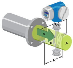
- The magnetic flowmeter operates based on Faraday’s Law of Electromagnetic Induction. When a conductive fluid passes through a magnetic field, it generates a voltage proportional to the fluid’s velocity. The voltage is then measured to determine the flow rate.
- The turbine flowmeter uses a mechanical method. As the fluid flows through the meter, it hits the blades of a turbine, causing the turbine to rotate. The rotation speed is directly proportional to the fluid velocity, and it is detected using an optical or magnetic sensor.
2. Conductivity Requirements
- Magnetic Flowmeter requires the fluid to be conductive. It is not suitable for measuring the flow of non-conductive fluids like oils and gases.
- No such conductivity requirements exist in the turbine flowmeter. It can measure both conductive and non-conductive fluids.
3. Installation and Orientation
- Magnetic Flowmeters are generally more flexible in installation orientation, as it doesn’t have any moving parts.
- The turbine flowmeter requires proper orientation to ensure that the turbine blades are not hindered, impacting measurement accuracy.
4. Pressure Drop
- Magnetic Flowmeter has minimal to no pressure drop because it lacks mechanical parts obstructing the flow.
- The turbine flowmeter may cause some pressure drop due to the presence of the mechanical turbine.
5. Accuracy and Sensitivity
- Magnetic Flowmeters are generally more accurate for conductive fluids and are less sensitive to variations in fluid properties.
- A turbine flowmeter can be very accurate but is sensitive to fluid viscosity and other properties, which might require frequent calibration.
6. Wear and Tear
- Magnetic Flowmeters have minimal wear and tear as there are no moving parts in contact with the fluid.
- Turbine flowmeter mechanical parts can wear out over time, especially when measuring abrasive or corrosive fluids.
7. Application Suitability
- Magnetic flowmeters are ideal for wastewater, slurries, and other conductive fluids.
- Turbine Flowmeter is suitable for clean, non-corrosive fluids, including oils and gases.
8. Cost
- Magnetic flowmeters are more expensive due to the electromagnetic technology involved.
- Turbine flowmeters are typically less expensive but may incur additional costs for maintenance and calibration.
Conclusion
Each flow meter type has its own advantages and drawbacks, and the appropriate selection often depends on specific application requirements. Always consider factors like fluid type, cost, and desired accuracy when choosing a flowmeter for your application.
If you liked this article, then please subscribe to our YouTube Channel for Instrumentation, Electrical, PLC, and SCADA video tutorials.
You can also follow us on Facebook and Twitter to receive daily updates.
Read Next:
- Flow Meter Calibration
- Averaging Pitot Tube
- Flow Meter Verification
- MPFM Working Principle
- Flow Transmitter Questions