Most forms of continuous flow measurement are inferential; that is, we measure flow indirectly by measuring some other variable (such as pressure, voltage, or frequency) directly. With this in mind, we may usually achieve reasonable calibration accuracy simply by calibrating the primary sensor and replacing the flow element (if inspection proves necessary).
Flow Standards
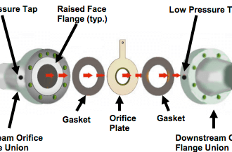
In the case of an orifice plate used to measure fluid flow rate, this would mean calibrating the differential pressure transmitter to measure pressure accurately and replacing the orifice plate if it shows signs of wear.
In some cases, though, direct validation of flow measurement accuracy is needed. Most techniques of flow rate validation take the form of measuring accumulated fluid volume over time. This may prove to be complicated, especially if the fluids in question are hazardous in any way, and/or the flow rates are large, and/or the fluid is a gas or vapor.
For simple validation of liquid flow rates, the flow may be diverted from its normal path in the process and into a container where either accumulated volume or accumulated weight may be measured over time. If the rate of flow into this container is constant, the accumulated volume (or weight) should increase linearly over time.
The actual flow rate may then be calculated by dividing the change in volume (ΔV ) by the time period over which the change in volume was measured (Δt). The resulting quotient is the average flow rate between those two points in time, which is an approximation of instantaneous flow rate:
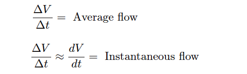
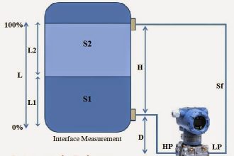
If a suitable vessel exists in the process with level-measuring capability (e.g. a liquid storage vessel equipped with a level transmitter), you may apply the same mathematical technique: use that vessel as an accumulator for the flow in question, tracking the accumulated (or lost) volume over time and then calculating ΔV/Δt .
The accuracy of this technique rests on some additional factors, though:
- The accuracy of the level transmitter (as a volume measuring instrument!)
- The ability to ensure only one flow path in or out of that vessel
The first condition listed here places significant limitations on the flow calibration accuracy one can achieve with this method. In essence, you are using the level instrument as the “test gauge” for the flow instrument, so it needs to be high-accuracy in order to achieve even reasonable accuracy for the flowmeter being calibrated.
A more sophisticated approach for direct flow validation is the use of a device called a flow prover. A “flow prover” is a precision piston-and-cylinder mechanism used to precisely measure a quantity of liquid over time.
Process flow is diverted through the prover, moving the piston over time. Sensors on the prover mechanism detect when the piston has reached certain positions, and time measurements taken at those different positions enable the calculation of average flow (ΔV/Δt ).
If you liked this article, then please subscribe to our YouTube Channel for Instrumentation, Electrical, PLC, and SCADA video tutorials.
You can also follow us on Facebook and Twitter to receive daily updates.
Read Next:
- What is an Orifice Flow Meter?
- Flow meter Turndown Ratio
- V Cone Flow Meter Principle
- Oval Gear Flow Meters
- Intrusive & Non-intrusive


Excellent Knowledge