Inst ToolsInst ToolsInst Tools
  • Courses
  • Automation
    • PLC
    • Control System
    • Safety System
    • Communication
    • Fire & Gas System
  • Instrumentation
    • Design
    • Pressure
    • Temperature
    • Flow
    • Level
    • Vibration
    • Analyzer
    • Control Valve
    • Switch
    • Calibration
    • Erection & Commissioning
  • Interview
    • Instrumentation
    • Electrical
    • Electronics
    • Practical
  • Q&A
    • Instrumentation
    • Control System
    • Electrical
    • Electronics
    • Analog Electronics
    • Digital Electronics
    • Power Electronics
    • Microprocessor
  • Request
Search
  • Books
  • Software
  • Projects
  • Process
  • Tools
  • Basics
  • Formula
  • Power Plant
  • Root Cause Analysis
  • Electrical Basics
  • Animation
  • Standards
  • 4-20 mA Course
  • Siemens PLC Course
Reading: Modbus Communication between Delta PLC with VFD
Share
Font ResizerAa
Inst ToolsInst Tools
Font ResizerAa
  • Courses
  • Design
  • PLC
  • Interview
  • Control System
Search
  • Courses
  • Automation
    • PLC
    • Control System
    • Safety System
    • Communication
    • Fire & Gas System
  • Instrumentation
    • Design
    • Pressure
    • Temperature
    • Flow
    • Level
    • Vibration
    • Analyzer
    • Control Valve
    • Switch
    • Calibration
    • Erection & Commissioning
  • Interview
    • Instrumentation
    • Electrical
    • Electronics
    • Practical
  • Q&A
    • Instrumentation
    • Control System
    • Electrical
    • Electronics
    • Analog Electronics
    • Digital Electronics
    • Power Electronics
    • Microprocessor
  • Request
Follow US
All rights reserved. Reproduction in whole or in part without written permission is prohibited.
Inst Tools > Blog > PLC Tutorials > Modbus Communication between Delta PLC with VFD

Modbus Communication between Delta PLC with VFD

In this article, we will learn the Modbus communication of delta PLC (DVP 14SS2) with delta VFD (VFD-L series) to control the motor speed.

Last updated: December 14, 2022 3:10 pm
Editorial Staff
PLC Tutorials
3 Comments
Share
8 Min Read
SHARE

Modbus communication of delta PLC (DVP 14SS2) with delta VFD (VFD-L series). The motor is to be run directly from HMI (DOP-107CV) using Modbus communication.

Contents
Delta PLC and VFD Modbus CommunicationCommunication ParametersPLC Program ExplanationHMIDelta PLC and VFD Control Program

Delta PLC and VFD Modbus Communication

  • The induction motor is to be run directly from HMI along with its speed control. Speed control is such that there should be two buttons in HMI that increase and decreases the speed of the motor by steps of one hertz (assume).
  • There is a VFD-L series delta AC drive which will run the motor based on the commands received from PLC.
  • Firstly, communication and other parameters need to be set in the drive matching all its configurations with the PLC such as baud rate, parity, communication mode, etc; except the slave ID (station address) which must be different from the PLC station address. By default, the PLC station address is equal to one (1). This means the station address of the drive must be anything in its defined range other than one (1).

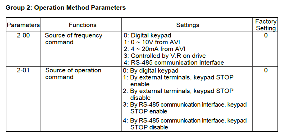
The detailed parameters to be set for the communication mode are as follows:

  • 2-00 = 4
  • 2-01 = 4
Delta PLC VFD communication mode

Communication Parameters

Delta PLC and VFD Communication Parameters

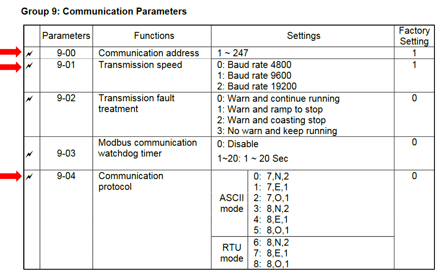
We have to set the communication parameters as per the above table. (taken from manual).

  • 9-00 = 2 (can be set to anything except 1)
  • 9-01 = 1
  • 9-04 = 7 (RTU mode, stop bits equal to 1 & parity to even)

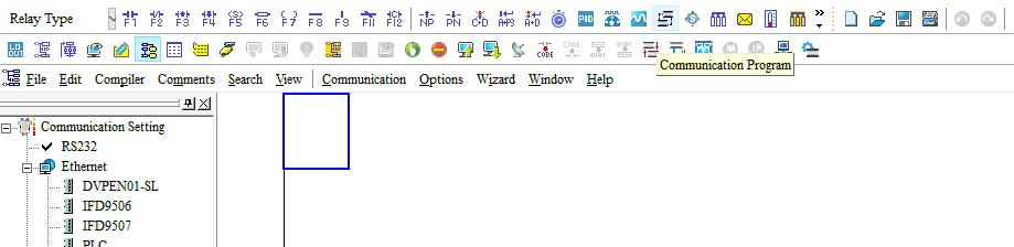
DVP 14SS2 has two communication ports namely RS232 and RS485 separately. Now, the communication port 2 settings need to be done according to the set parameters of VFD which are as follows.

  • Open the WPL soft. (Delta PLC Software)
  • Click on the Communication Program icon on the programming page.
Open the WPL soft

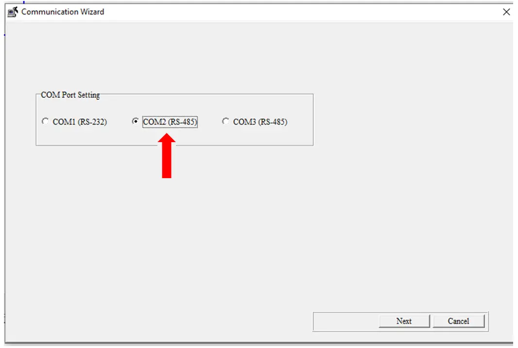
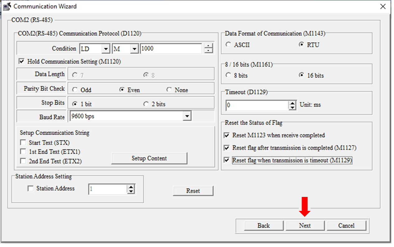
Select COM2 and press next.

Delta PLC Communication Wizard

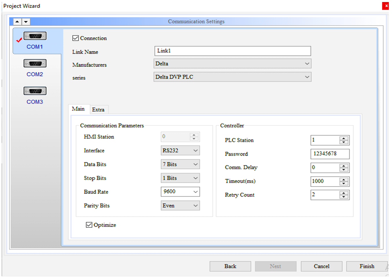
Set the parameters according to the VFD drive communication parameters and click Next. Here, they are fed according to the parameters set in the VFD-L dive.

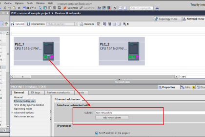
The station address of PLC is 1 (see left bottom corner)

Delta PLC Communication Protocol

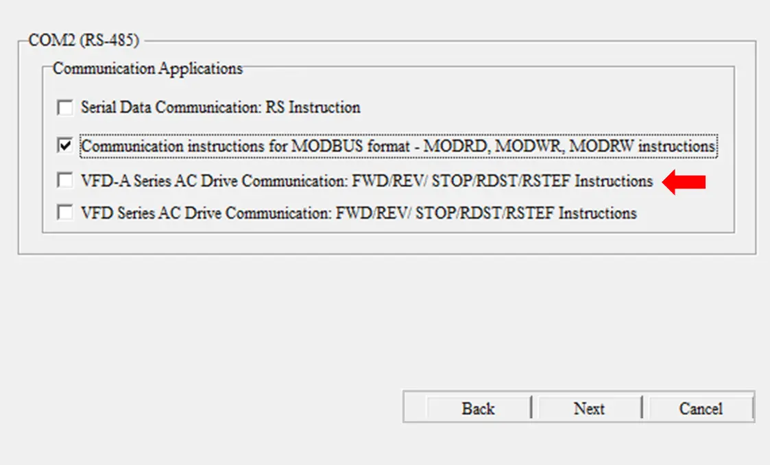
Check the highlighted and press next.

Delta PLC Communication Instructions for Modbus Format

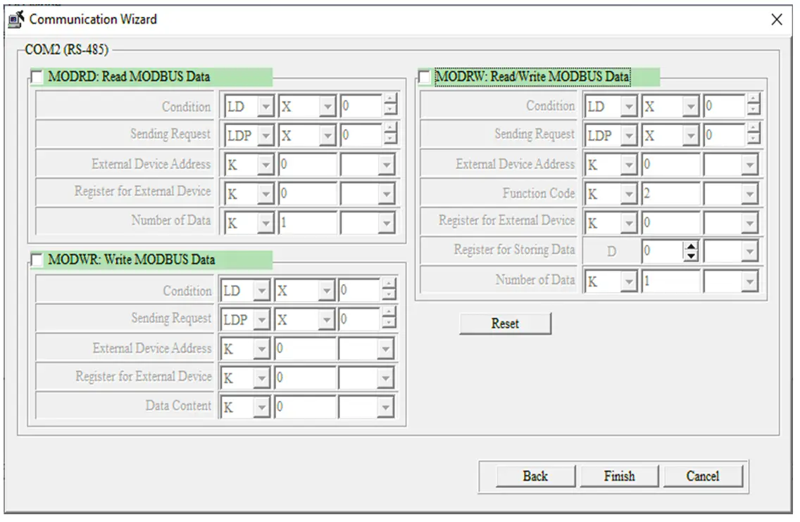
One can check the boxes below and write the conditions.

Here, we are skipping this window, and instead, we will write the logic directly on ladder diagram mode.

Click Finish.

Delta PLC Modbus Read and Write Data

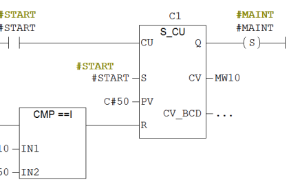
Now, the following ladder logic is generated as a result of the above set conditions.

Modbus Communication between Delta PLC with VFD
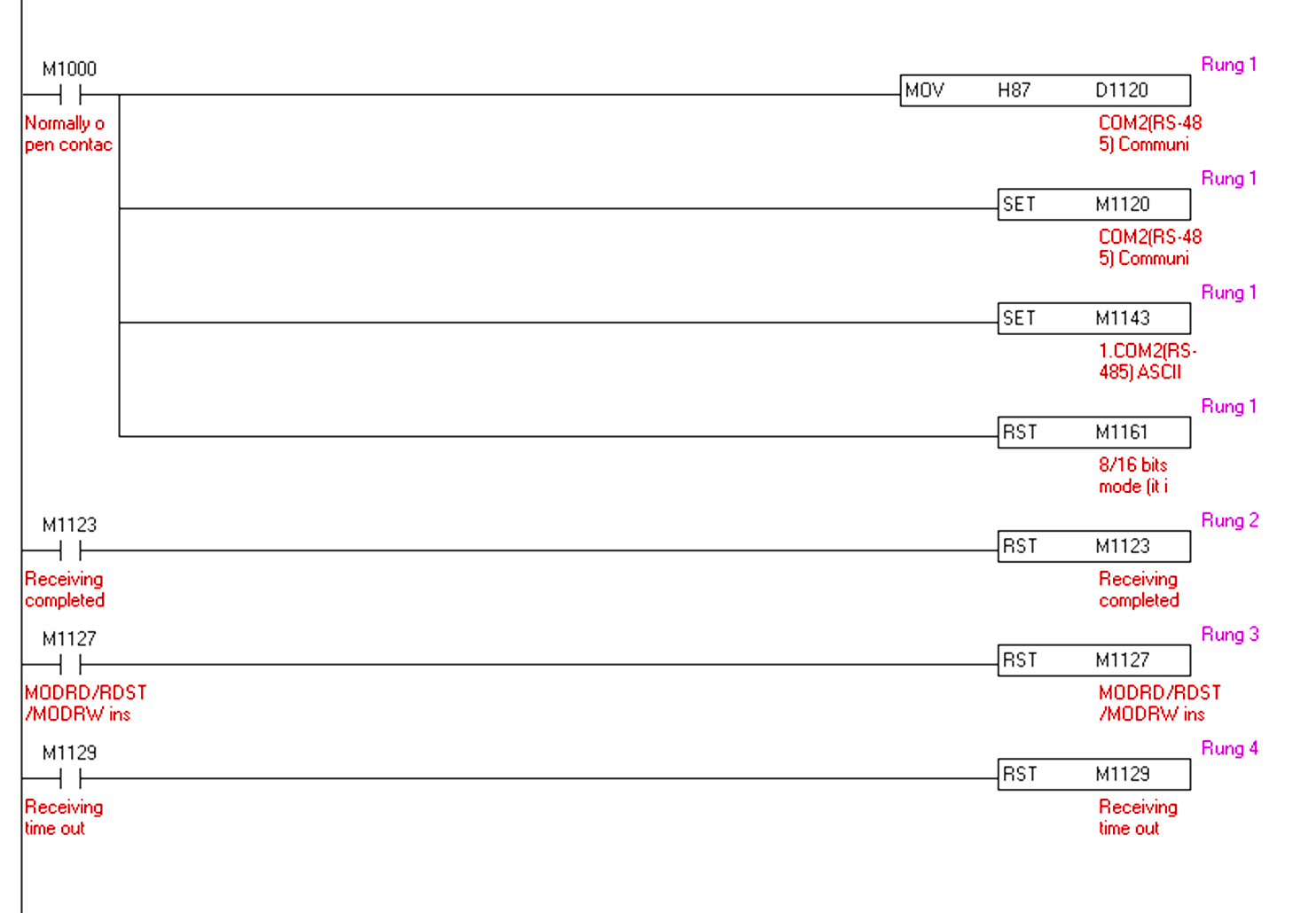
  • The ladder in rung 2 executes each time a sent request is received.
  • The ladder in rung 3 executes each time after any data is read from or written to the drive.

  • Now, before moving further, the logic for starting and stopping the motor and its speed control is written, we need to find out the Modbus addresses of the drive through which the said will be executed.
  • For the VFD-L series, 2000H is the Modbus address for starting & stopping the drive and 2001H is for the frequency change. Here, H denotes hexadecimal.

In this topic, we are here to use the decimal format for the particular address. So hexadecimal must be changed to decimal format.

Through the 8421 code, we would convert as follows:

  • 2000 (Hex) = 8192 (Dec)
  • 2001(Hex) = 8193 (Dec)

So, instead of 200H & 2001H, 8192K & 8193K will be used. Make sure that 8192 & 8193 are only the Modbus addresses.

  • If 8192K has a value equal to 10 then the motor will start.
  • If 8192K has a value equal to 1 then the motor will stop.
  • If 8193K has a value equal to 5000 then the motor will run on 50 Hz, which means if the speed of the motor needs to be increased by 1 Hz, 100 must be added to the existing value and vice versa.

PLC Program Explanation

  • Now, going to the details of the PLC program.
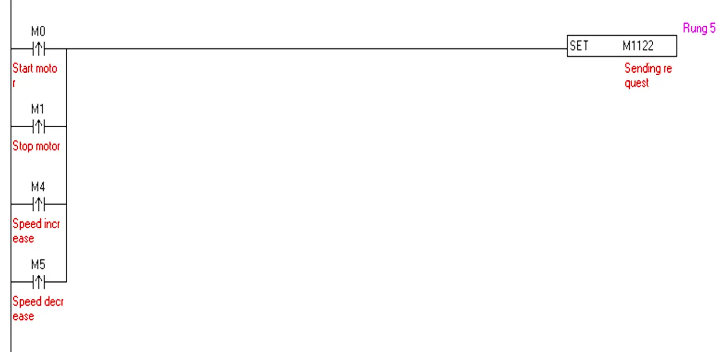
  • Sending request bit M1122 is set each time any command is given to VFD in rung 5.
PLC & VFD MODBUS Communication

MODRW K2 K6 K8192 D70 K1

  • MODRW represents Mod read write
  • K2 represents the station address of the VFD.
  • K6/K3 represents the function code whether to write or read. Here k6 represents write.
  • K8192 represents the Modbus address to which data is written
  • Data in D70 is written to k8192
  • K1 is the data length
Delta PLC to VFD Modbus

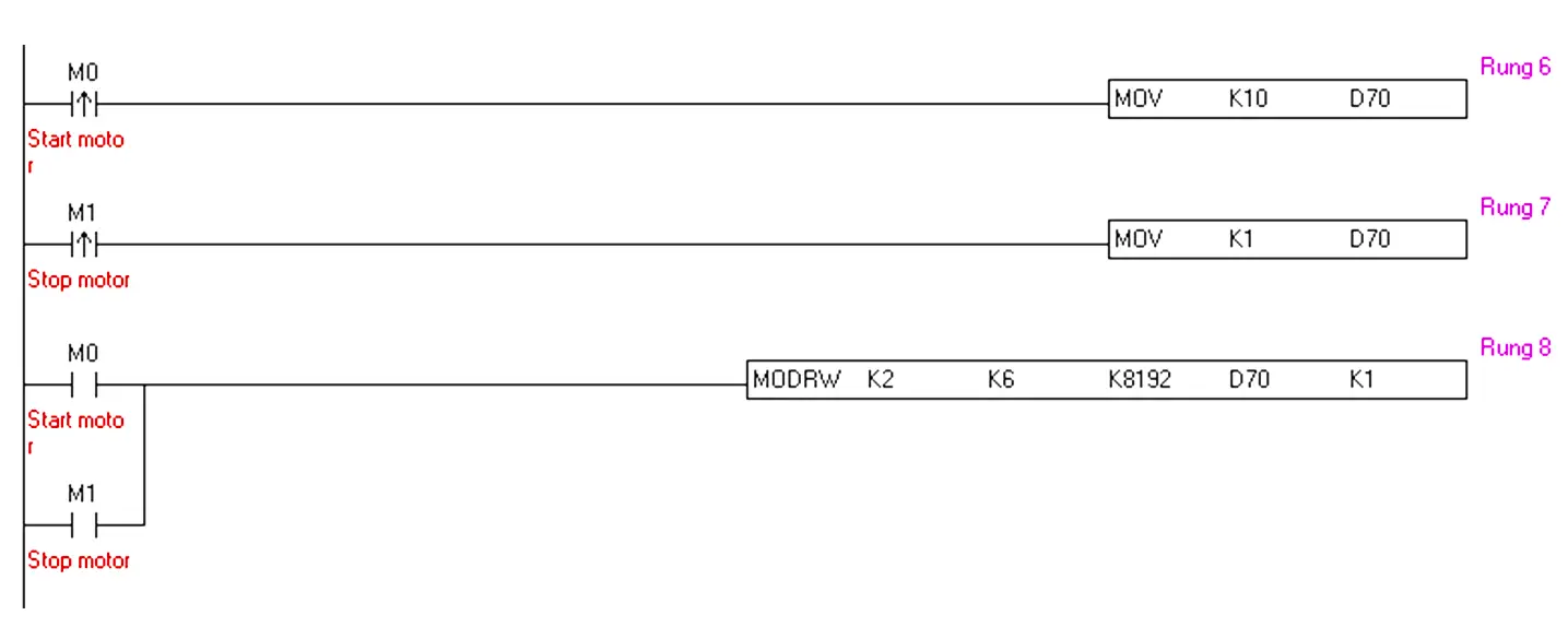
10 (dec) and 1 (dec) are moved to D70 when start and stop commands are given in rungs 6 and 7. At the same time, the transmission of data takes place i.e data in D70 is written to the 8192k address of VFD in rung 8 to start and stop the motor.

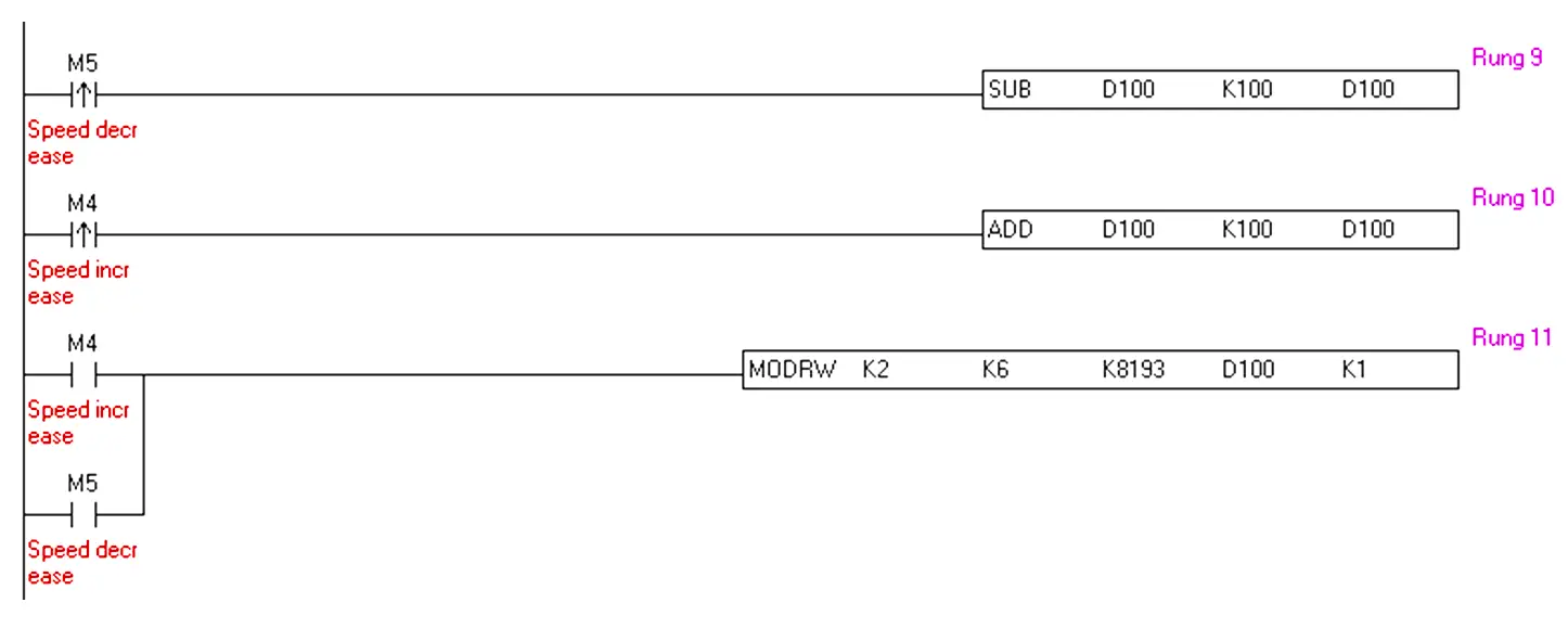
100 (dec) is added to D100’s value in rung 10 to increase the speed by 1 Hz when the speed increase pulse (M4) is received. 100 (dec) is subtracted from D100’s value in rung 9 to decrease the speed by 1 Hz when the speed decrease pulse (M5) is received.

At the same time, the transmission of data takes place i.e data in D100 is written to the 8193k address of VFD in rung 11 to start and stop the motor.

Delta PLC Modbus program example

HMI

Now, coming to the HMI configuration.

After selecting the HMI model, set the below configuration as here, PLC to HMI configuration is on RS232. (You have to configure it as per the HMI model)

Delta PLC VFD HMI configuration

Take four momentary buttons, assign the addresses, and design the HMI screen as follows:
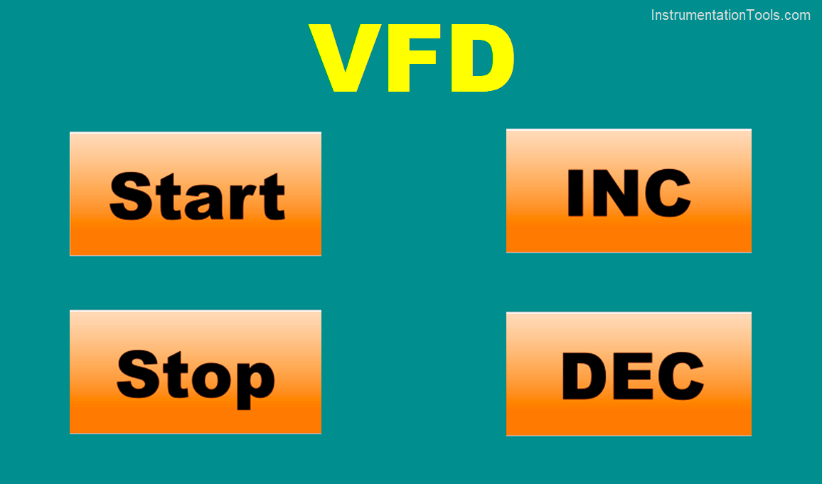
HMI configuration for Delta VFD
  • Start = M0
  • Stop = M1
  • Increase speed = M4
  • Decrease speed = M5
  • Test the process

The HMI design is not covered in this article.

Delta PLC and VFD Control Program

The below Delta PLC and VFD training topic is shared for your understanding. This is another way of controlling the motor speed via Delta PLC using ISPsoft.

VFD Control using PLC and HMI - Automation Training

If you liked this article, then please subscribe to our YouTube Channel for Instrumentation, Electrical, PLC, and SCADA video tutorials.

You can also follow us on Facebook and Twitter to receive daily updates.

Read Next:

  • Design of PLC System
  • How to Choose a SCADA?
  • Compare NO and NC Contacts
  • SCADA System Vulnerabilities
  • Inputs and Outputs in Delta PLC
Don't Miss Our Updates
Be the first to get exclusive content straight to your email.
We promise not to spam you. You can unsubscribe at any time.
Invalid email address
You've successfully subscribed !

Continue Reading

Types of Expressions in the SCL Language of the Tia Portal
Motor Trip Logic using PLC Programming
Using Clock Memory Bits in TIA Portal – Siemens PLC
SFC Language in PLC Programming
Principle of Operation of PLC
Elevator PLC Ladder Logic
Share This Article
Facebook Whatsapp Whatsapp LinkedIn Copy Link
Share
3 Comments
  • Ravi Shankar says:
    June 4, 2023 at 3:30 pm

    Hello Sir,
    Sir your blog is good and interested can you please write a blog on delta b2 servo motor modbus communication with plc

    Reply
    • Muhammad Wasay Zia says:
      June 5, 2023 at 11:46 am

      Thanks mama….We are here to help you… If you want we can also make your project.

      Reply
  • Fawaz Rahman Azeez says:
    March 20, 2025 at 2:15 pm

    what should be done incase there are 2 vfd to be programmed in wplsoft. i do understand the m register will be different to start stop and all. what about the modbus address dec number to transfer the data?

    Reply

Leave a Reply Cancel reply

Your email address will not be published. Required fields are marked *

Stay Connected

128.3kFollowersLike
69.1kFollowersFollow
210kSubscribersSubscribe
38kFollowersFollow

Categories

Explore More

Siemens Drum block for Sequencer Operation
D Flip Flop PLC Ladder Logic
Basics of PLC Programming
Node-RED in PLC Industrial Automation
How to Add Security in InTouch SCADA?
PLC Crane Movement Control with Limit Switches
How to take Backup from Siemens S7-300 PLC?
DeMorgan’s Theorems using Ladder Diagram

Keep Learning

Turbine-Compressor System Architecture

Turbine-Compressor System Architecture

PLC Logic for Water Pumping and Chemical Addition

Developing PLC Logic for Water Pumping and Chemical Addition

What is the consumed tag in Studio 5000 software?

Produced Tags and Consumed Tags in Studio 5000

On Delay Timer using PLC

ON Delay Timer using PLC

Power Supply Sizing for Industrial Automation Systems

Power Supply Sizing for Industrial Automation Systems

PLC Programming Example on Bottle Line Control

PLC Programming Example on Bottle Line Control

Simple Conveyor Control PLC Program

XG5000 Example of Simple Conveyor Control PLC Program

Group of Induction Motors

How to Operate a Group of Induction Motors using PLC Logic?

Learn More

Basic Pneumatic System

Introduction to Fluid Power and Pneumatics

Marshalling Panel

What is Marshalling Cabinet?

Displacer interface level measurement Calibration

Displacer Interface Level Measurement

What is a Mimic Panel

What is a Mimic Panel ?

What is VLAN?

Difference Between Subnet and VLAN

PLC Timer Programming Examples on Coffee Machine

PLC Timer Practice Exercise: Coffee Machine Programming

Temperature Measurement Multiple Choice Questions

Temperature Measurement Multiple Choice Questions

HMI screen for operator

#8 PLC Best Practices – Validate HMI Input Variables at PLC Level

Menu

  • About
  • Privacy Policy
  • Copyright

Quick Links

  • Learn PLC
  • Helping Hand
  • Part Time Job

YouTube Subscribe

Follow US
All rights reserved. Reproduction in whole or in part without written permission is prohibited.
Welcome Back!

Sign in to your account

Username or Email Address
Password

Lost your password?