Inst ToolsInst ToolsInst Tools
  • Ask
  • Courses
  • Videos
  • Q & A
    • Interview
      • Instrumentation
      • Electronics
      • Electrical
      • Practical Questions
    • MCQ
      • Instrumentation MCQ
      • Electrical MCQ
      • Electronics MCQ
      • Control Systems MCQ
      • Analog Electronics MCQ
      • Digital Electronics MCQ
      • Power Electronics MCQ
      • Microprocessor MCQ
      • Multiple Choice Questions
  • EE
    • Electronics
      • Electronics Q & A
      • Electronic Basics
      • Electronic Devices & Circuits
      • Electronics Animation
      • Digital Electronics
    • Electrical
      • Electrical Basics
      • Electrical Q & A
      • Power Electronics
      • Electrical Machines
      • Electrical Animation
      • Power Systems
      • Switchgear & Protection
      • Transmission & Distribution
  • Measure
    • Control Valves
    • Calibration
    • Temperature
    • Pressure
    • Flow
    • Level
    • Analyzers
    • Switches
    • Vibration
    • Solenoid Valve
  • Control
    • PLC Tutorials
    • Control Systems
    • Safety Instrumented System (SIS)
    • Communication
    • Fire & Gas System
  • More
    • Design
    • Tools
    • Animation
    • Basics
    • Formulas
    • Standards
    • TextBooks
    • Common
    • Software
    • Excel Tools
    • Erection & Commissioning
    • Process Fundamentals
    • Videos
    • Books
Search
All rights reserved. Reproduction in whole or in part without written permission is prohibited.
Reading: Root Cause Analysis for Vibration Probe Not Responding
Share
Notification Show More
Font ResizerAa
Inst ToolsInst Tools
Font ResizerAa
  • Courses
  • PLC Tutorials
  • Control Systems
Search
  • Ask
  • Courses
  • Videos
  • Q & A
    • Interview
    • MCQ
  • EE
    • Electronics
    • Electrical
  • Measure
    • Control Valves
    • Calibration
    • Temperature
    • Pressure
    • Flow
    • Level
    • Analyzers
    • Switches
    • Vibration
    • Solenoid Valve
  • Control
    • PLC Tutorials
    • Control Systems
    • Safety Instrumented System (SIS)
    • Communication
    • Fire & Gas System
  • More
    • Design
    • Tools
    • Animation
    • Basics
    • Formulas
    • Standards
    • TextBooks
    • Common
    • Software
    • Excel Tools
    • Erection & Commissioning
    • Process Fundamentals
    • Videos
    • Books
Follow US
All rights reserved. Reproduction in whole or in part without written permission is prohibited.
Inst Tools > Blog > Root Cause Analysis (RCA) > Root Cause Analysis for Vibration Probe Not Responding

Root Cause Analysis for Vibration Probe Not Responding

In this article, we discussed the root cause analysis of a centrifugal compressor vibration probe that is not responding.

Last updated: September 30, 2022 12:07 pm
Editorial Staff
Root Cause Analysis (RCA) Vibration Measurement
3 Comments
Share
6 Min Read
SHARE

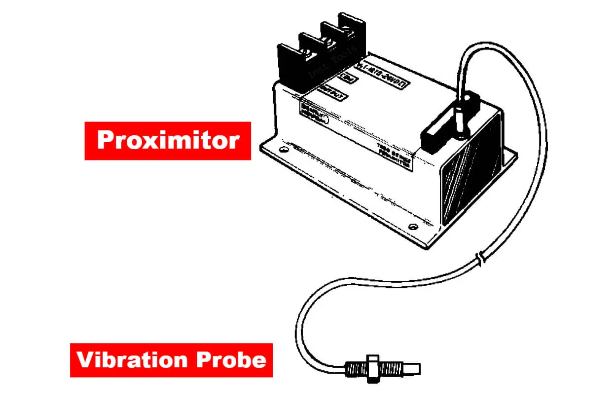
Today in this article we will discuss about one incident that occurred in a plant where a vibration probe was installed for the centrifugal compressor.

Contents
Vibration Probe Problem StatementRoot Cause Analysis for Vibration ProbeObservationsWhat went wrong?

The vibration probe was ok, but still, the vibration probe was not responding to the actual vibrations in the compressor.

Vibration Probe Problem Statement

A centrifugal compressor installed in one plant had 2 vibration probes installed per stage. The compressor was opened for planned maintenance activities and all the instruments were removed.

Root Cause Analysis for Vibration Probe

After the box-up of the compressor, the compressor was started. After the compressor start-up, 30 minutes later one observation came.

For one particular stage, one probe (Probe X) was showing vibrations of 0.5 mm/sec while another probe (Probe Y) was showing a constant reading of 0 mm/sec.

After 15 more minutes, Probe Y went to an alarm level of 0.9 mm/sec while probe X was still at 0 mm/sec. Immediately, the compressor was stopped for inspection.

Root Cause Analysis for Vibration Probe

So what can be the probable reason for vibration probe X not responding?

Probable Problem 1: Vibration probe X became faulty.

This probable problem is ruled out as during linearity check and response check, the system responded satisfactorily. Also, the resistance of the vibration probe was ok.

Probable Problem 2: The extension cable of vibration probe X became faulty.

This problem was ruled out as, during linearity check and response check, the system found ok. Also, the resistance of the extension cable was ok.

Bently Nevada Proximity Probe

Probable Problem 3: Proximitor became faulty

This problem was also ruled out as, during linearity check and response check, the system response was found ok.

Probable Problem 4: No vibrations in the compressor

This problem rules out as vibration probe Y captured vibrations and after opening the compressor, the mechanical team found the problem.

Probable Problem 5: The gap voltage was not set properly.

This problem was ruled out because before removing the vibration probe, the gap voltage was checked and found ok.

Probable Problem 6: Loose connection in the vibration probe system

This problem was ruled out as, during the response check of the system, the system was found ok.

Probable Problem 7: Standard Maintenance Procedure for setting gap voltage not followed

This might be the probable reason as everything else was found ok.

Observations

Observations after opening the compressor again:

  1. Mechanically department opened the compressor and found the issue on the impellor side (this decision came because in past also vibrations were high for that particular stage).
  2. The instrumentation team checked both vibration probe gap voltage and found ok.
  3. Resistance of both vibration probes, both extension cables checked. All found ok.
  4. Both vibration probe’s linearity and found ok.
  5. Vibration probe X’s response was checked with calibrator TK-3e and found ok.
  6. Physically also both vibration probes were ok. But for vibration probe X, some dust particles were present on the tip of the vibration probe. Also during the reinstallation job of the vibration probe, the standard maintenance procedure was not followed.

What went wrong?

Before removing the vibration probe after the problem occurred, the length (length outside the compressor) of the vibration probe was noted down.

After checking everything and declaring all three elements ok i.e. vibration probe, extension cable, and proximitor.

The vibration probe was again inserted.  This time the insertion length was more as compared to the length which was noted before removing the vibration probe.

On discussion with the technician who inserted the vibration probe after the compressor shutdown, he told that he did not push the vibration probe inside till the tip of the vibration probe touched the shaft.

The standard procedure for setting gap voltage is to first insert the vibration probe fully till it touches the shaft or the body whose vibration is to be measured. This is done to remove the magnetic effect on the vibration probe due to the surrounding. 

So the technician directly inserted the vibration probe and in between somewhere on the threading, there was foreign material which was found on the probe tip. Because of this material, the vibration probe’s gap voltage became ok.

But actually, the vibration probe was far away from the shaft. Hence the actual vibrations of the shaft were not captured by the vibration probe.

So minor foreign particles, as well as standard maintenance procedures (SMP) not being followed, were the two main reasons for this cause.

Don't Miss Our Updates
Be the first to get exclusive content straight to your email.
We promise not to spam you. You can unsubscribe at any time.
Invalid email address
You've successfully subscribed !
A Large Gate Valve’s Failed Motorized Operation
Stuck Segment Orifice Dimensions Calculations
Erratic H2 Flow Rotameter
Aluminum Cable Terminations Repeat Failures
RCA Related to Trip Throttle Valve (TTV)
Share This Article
Facebook Whatsapp Whatsapp LinkedIn Copy Link
Share
3 Comments
  • Santosh says:
    February 15, 2024 at 10:46 am

    Root causes of vibration probe

    Reply
    • Shahid says:
      June 20, 2024 at 11:49 am

      Hi Santosh, this is indeed a very good case study. However the initial content of this case study requires to be revisited & checked for correction. Initially Article says that X probe is fine & Y probe having issue but later on the article confused with saying that X probe is having problem & Y probe is fine.
      Regards

      Shahid
      ISO CAT IV Mobius.

      Reply
  • Ahmed says:
    July 3, 2024 at 3:08 pm

    There’s a bad mood reading for the proximity sensor when installing on the bum…, change the sensor and cable same problem…, what the reason!!?

    Reply

Leave a Reply Cancel reply

Your email address will not be published. Required fields are marked *

Stay Connected

128.3kFollowersLike
69.1kFollowersFollow
208kSubscribersSubscribe
38kFollowersFollow

Categories

Recent Comments

  • Kamli on Top Free PLC Software
  • Guifty Shimica on Top Non-PLC Certification Courses for Automation Professionals
  • Guifty Shimica on Top Non-PLC Certification Courses for Automation Professionals
  • MIHARITSOA Aina Sitraka on Top Non-PLC Certification Courses for Automation Professionals

Related Articles

Compressor IP Case Discharge Temperature Gradually Increases

Compressor Anti-Surge Control near-miss incident

Testing of Pneumatic Systems

Panel and Field Pneumatic Controller’ Bumpless Transfer Issues

Proximity Transducer Operation

Proximity Transducer System Operation

Reformer Fan Bearing Change Times cut by 90%

Reformer Fan Bearing Change Times cut by 90%

Inlet Pigtail

Primary Reformer – Each Turnaround done expensive Tubes Repairs

Unstable & Drifting Values of Differential Pressure Transmitter

Unstable & Drifting Values of Differential Pressure Transmitter Problem

Under and Over-Capacity Control Valve

Under and Over-Capacity Control Valve Pose Poor Controllability

Captive Power Plant Trip Root Cause Analysis

Captive Power Plant Trip Root Cause Analysis

More Articles

Inductive Transducers Objective Questions

Inductive Transducers Objective Questions

Chemical Sensors Objective Questions

Chemical Sensors Objective Questions

What is NEST loading in DCS

What is Nest Loading? – DCS and PLC Control Systems

Safety Relief Valve Material Selection

Burst Transformers Root Cause Analysis

Root Cause Analysis – Burst Transformers and 11 kV Input Breakers

High-Speed Inputs in PLC

What are High-Speed Inputs in PLC?

field-mounted thermocouple

Thermocouple Extension Wires

Sulfur Hexafluoride Gas (SF6) Properties

Sulfur Hexafluoride Gas (SF6) Properties

Follow US
All rights reserved. Reproduction in whole or in part without written permission is prohibited.
Welcome Back!

Sign in to your account

Username or Email Address
Password

Lost your password?