Inst ToolsInst ToolsInst Tools
  • Courses
  • Automation
    • PLC
    • Control System
    • Safety System
    • Communication
    • Fire & Gas System
  • Instrumentation
    • Design
    • Pressure
    • Temperature
    • Flow
    • Level
    • Vibration
    • Analyzer
    • Control Valve
    • Switch
    • Calibration
    • Erection & Commissioning
  • Interview
    • Instrumentation
    • Electrical
    • Electronics
    • Practical
  • Q&A
    • Instrumentation
    • Control System
    • Electrical
    • Electronics
    • Analog Electronics
    • Digital Electronics
    • Power Electronics
    • Microprocessor
  • Request
Search
  • Books
  • Software
  • Projects
  • Process
  • Tools
  • Basics
  • Formula
  • Power Plant
  • Root Cause Analysis
  • Electrical Basics
  • Animation
  • Standards
  • 4-20 mA Course
  • Siemens PLC Course
Reading: How to do calibration checks of vibration Probe, extension cable and vibration monitor
Share
Notification Show More
Font ResizerAa
Inst ToolsInst Tools
Font ResizerAa
  • Courses
  • Design
  • PLC
  • Interview
  • Control System
Search
  • Courses
  • Automation
    • PLC
    • Control System
    • Safety System
    • Communication
    • Fire & Gas System
  • Instrumentation
    • Design
    • Pressure
    • Temperature
    • Flow
    • Level
    • Vibration
    • Analyzer
    • Control Valve
    • Switch
    • Calibration
    • Erection & Commissioning
  • Interview
    • Instrumentation
    • Electrical
    • Electronics
    • Practical
  • Q&A
    • Instrumentation
    • Control System
    • Electrical
    • Electronics
    • Analog Electronics
    • Digital Electronics
    • Power Electronics
    • Microprocessor
  • Request
Follow US
All rights reserved. Reproduction in whole or in part without written permission is prohibited.
Inst Tools > Blog > Calibration > How to do calibration checks of vibration Probe, extension cable and vibration monitor

How to do calibration checks of vibration Probe, extension cable and vibration monitor

How to do calibration checks of vibration Probe, extension cable and vibration monitor in the bently nevada machine monitoring system.

Last updated: October 5, 2020 1:44 pm
Editorial Staff
Calibration Vibration Measurement
19 Comments
Share
2 Min Read
SHARE

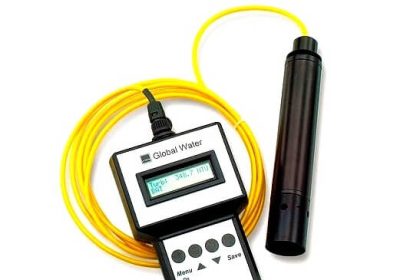
Calibration checks of vibration Probe, extension cable and vibration monitor

vibration-probe-calibration

Calibration Procedure:

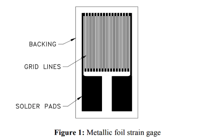
1. Physical check of vibration probe and extension cable for any damages, if it is please replaced with same one.

2. Check resistance of vibration probe and continuity of extension cable it should be 5 to 9Ω and 5 to 20 Ω

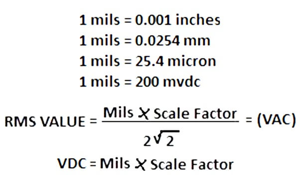
3. Use below equation and get reading for calibration of vibration probe.

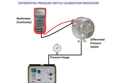
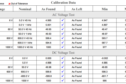
4. Connect test equipment.

5. Adjust the spindle micrometer on the TK-3 test and calibration kit shown 0.51 mm (20 mils) (0.0254mm=1mils).

6. Insert the probe in to the TK-3 probe holder adjust the probe in the holder until the digital multimeter shows -3.00 ±0.10 VDC.

7. Adjust the micrometer to 0.20mm (8 mils) indication and the back it out again to the 0.25mm (10 mils) indication backless in the micrometer forced the o/p voltage and record it.

8. Increase the gap in 0.25 (10mils) increment by adjusting the micrometer record the voltage indication at each increment.

9. For each gap increment subtract the voltage at the high gap from the voltage at the low gap divide the result by in a system incremental scale factor of 7.87 ±0.79 v/mm (200 mv ±20 mv/mils).

10. Subtract the 0.25 mm (10 mils) voltage (-5 vdc) from the 2.28 mm (90 mils) (11 vdc) and divided by 2.03mm (80 mils). The result should ina system average scale factor (ASF) of 7.87 ±0.43 v/mm (200 mv ±11 mv/mils).

Author: D.Chakraborty

Read Next:

  • Accelerometer Vibration Sensor
  • Gap Voltage Procedure
  • Bently Nevada Vibration Probes Functional Testing
  • Interview Questions on Vibration Measurement
  • Importance of Vibration Measurement
Don't Miss Our Updates
Be the first to get exclusive content straight to your email.
We promise not to spam you. You can unsubscribe at any time.
Invalid email address
You've successfully subscribed !

Continue Reading

Top 100 Vibration Analysis Questions and Answers
Differential Pressure Sensors Calibration Procedure
Magnehelic Gauge Calibration
Calibration Procedure of Weighing Balance and Common Mistakes
Functional Testing of Control Valve Positioners
RTD Testing Methods in Calibration Laboratory
Share This Article
Facebook Whatsapp Whatsapp LinkedIn Copy Link
Share
19 Comments
  • banny says:
    September 28, 2015 at 2:57 am

    Hello, I enjoy reading all of your articles. I like to write a little comment to support you.

    Reply
    • asim says:
      January 29, 2016 at 7:19 am

      Hi i am Asim i want to say that if you can add video on it student can Learn much easier

      Reply
      • S Bharadwaj Reddy says:
        January 29, 2016 at 8:43 am

        Hello Asim, You are right, But Videos takes lot of time and its difficult for me to spend more time.

        Reply
  • ranjan.k.k says:
    October 27, 2015 at 5:08 am

    buddy, you have explained everything with such a simplicity that even a guy who is not from this field can understand. i really enjoyed reading all your articles also i had recommended this site to my friends who are new in instrumentation and have lots of queries about working of instrumentation. thanks for putting lots of effort. god bless you

    Reply
  • rohith says:
    December 2, 2015 at 5:19 am

    Very good explained .. i very like this site .thank you ….

    Reply
  • Sriram says:
    January 6, 2016 at 7:56 pm

    What is the scale factor
    How to calculate the values

    Reply
  • m r ravichandran says:
    March 11, 2016 at 7:06 am

    sir, can you please explain wouplater in tk3 with probe calibration. as you said the supply voltage is -24vdc,whether the output also will be in negative voltage please reply

    Reply
  • jayesh says:
    April 29, 2016 at 9:13 am

    how i set key phasor in turbine

    Reply
    • Farooq says:
      October 26, 2019 at 5:35 pm

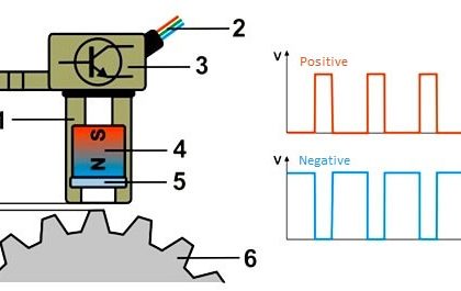
      It can be set same as radial probe with the electrical voltage gap -8 VDC to -12VDC. But first you make sure that the notch/ grove on shaft should not in front of probe tip.

      Reply
  • manikandan R says:
    May 9, 2016 at 5:58 am

    Dear sir, thank u for ur
    good explanation and procedure for vibration sensor calobration

    Reply
  • Hiren patel says:
    May 18, 2016 at 4:09 pm

    It is very clearly explain

    Reply
  • rajkumar.j says:
    August 7, 2016 at 10:47 am

    very useful for vibration calibration techs…

    Reply
  • djafer says:
    January 5, 2017 at 10:55 am

    Dear all;

    Please, can you explain me extension cable length, proximitor length and prob length.

    [email protected]

    Regards

    Reply
  • Hemant says:
    January 25, 2017 at 2:48 am

    Sir I m u r fan,one question. In para 3 u tell adjust 3v for 20mile & para 10, 5 v for 10mile how.voltage less than 3v.plese explain.thanks

    Reply
  • Hemant says:
    January 25, 2017 at 2:51 am

    In para 3 u tell adjust 3 v for 20 mile,para 10,10mile get5v how sir

    Reply
  • ahmed messallam says:
    March 13, 2017 at 11:28 am

    valuable information, can you give some vendors that produce vibration test equipment.

    Reply
  • Rohith says:
    September 27, 2018 at 5:33 pm

    Sir
    If during loop checking how can I calculated. I can measure out value of transducer in MVac. How can I calculated or concert this MVac to mils what formula we can use. So kindly request you please explain my doubts…

    Thanks
    Tinu Mathew

    Reply
  • praveen kumar says:
    May 12, 2020 at 5:22 pm

    why the output of the average scale factor is 7.87v/mm.. why not above or below… is that any calculation behind the value..?

    Reply
  • Mahmoud says:
    September 20, 2022 at 2:37 pm

    Standard 9 meter
    System
    7.87 V/mm (200 mV/mil) ± 6.5%
    including interchangeability error
    when measured in increments of
    0.25 mm (10 mils) over the 80 mil
    linear range from 0 °C to +45 °C
    (+32 °F to +113 °F).

    Reply

Leave a Reply Cancel reply

Your email address will not be published. Required fields are marked *

Stay Connected

128.3kFollowersLike
69.1kFollowersFollow
210kSubscribersSubscribe
38kFollowersFollow

Categories

Explore More

How to Calibrate the Eddy Current Conductivity Meter?
Error sources creating uncertainty in Calibration
Selection of Weighing Balance and Weight for Calibration
Calibration of Weight using the ABBA Method
Smart Transmitter Calibration Tutorial Part 1
Basics of Calibration
DP Level Transmitter with Zero Suppression Calibration
Stability and Uniformity of Temperature Bath

Keep Learning

List of Documents Required for Testing and Calibration Laboratory

List of Documents Required for Testing and Calibration Laboratories

DP Diaphragm Capillary Seal Level instrument

DP Diaphragm Capillary Seal Level instrument Calibration Procedure

Uncertainty Calculations of Pressure Calibration

Uncertainty Calculations of Pressure Calibration

Magnetostrictive Level Transmitter Calibration

Magnetostrictive Level Transmitter Calibration Procedure

Pressure transmitter Calibration Setup

Instruments Calibration Procedures

Why Calibration is Important

Why Calibration is Important?

Wireless HART Transmitter

How to Commission WirelessHART Transmitter With Gateway

Advantages and Disadvantages of Network Topology

Advantages & Disadvantages of Different Vibration Sensors

Learn More

Car Parking System using PLC Programming

Car Parking System using PLC Programming

Control Valve Tips and Tricks

Control Valve Tips and Tricks

Electrical Machines Questions and Answers

Synchronous Machines Distributed Winding Quiz

orifice plate vent hole

What is the Purpose of Orifice Plate Drain Hole and Vent Hole?

Calibration setup for a low-range electronic pressure transmitter

Instrument Lab Exercise – Ranging and Manometer Usage

PLC Program for Automatic Oil and Water Separation Process

Oil and Water Separation Process using PLC Programming

Advantages and Applications of zigzag transformer

SR Flip Flop Logic

How to implement SR Flip Flop using PLC Ladder Logic

Menu

  • About
  • Privacy Policy
  • Copyright

Quick Links

  • Learn PLC
  • Helping Hand
  • Part Time Job

YouTube Subscribe

Follow US
All rights reserved. Reproduction in whole or in part without written permission is prohibited.
Welcome Back!

Sign in to your account

Username or Email Address
Password

Lost your password?