Inst ToolsInst ToolsInst Tools
  • Ask
  • Courses
  • Videos
  • Q & A
    • Interview
      • Instrumentation
      • Electronics
      • Electrical
      • Practical Questions
    • MCQ
      • Instrumentation MCQ
      • Electrical MCQ
      • Electronics MCQ
      • Control Systems MCQ
      • Analog Electronics MCQ
      • Digital Electronics MCQ
      • Power Electronics MCQ
      • Microprocessor MCQ
      • Multiple Choice Questions
  • EE
    • Electronics
      • Electronics Q & A
      • Electronic Basics
      • Electronic Devices & Circuits
      • Electronics Animation
      • Digital Electronics
    • Electrical
      • Electrical Basics
      • Electrical Q & A
      • Power Electronics
      • Electrical Machines
      • Electrical Animation
      • Power Systems
      • Switchgear & Protection
      • Transmission & Distribution
  • Measure
    • Control Valves
    • Calibration
    • Temperature
    • Pressure
    • Flow
    • Level
    • Analyzers
    • Switches
    • Vibration
    • Solenoid Valve
  • Control
    • PLC Tutorials
    • Control Systems
    • Safety Instrumented System (SIS)
    • Communication
    • Fire & Gas System
  • More
    • Design
    • Tools
    • Animation
    • Basics
    • Formulas
    • Standards
    • TextBooks
    • Common
    • Software
    • Excel Tools
    • Erection & Commissioning
    • Process Fundamentals
    • Videos
    • Books
Search
All rights reserved. Reproduction in whole or in part without written permission is prohibited.
Reading: What is TK-3 Calibrator ?
Share
Notification Show More
Font ResizerAa
Inst ToolsInst Tools
Font ResizerAa
  • Courses
  • PLC Tutorials
  • Control Systems
Search
  • Ask
  • Courses
  • Videos
  • Q & A
    • Interview
    • MCQ
  • EE
    • Electronics
    • Electrical
  • Measure
    • Control Valves
    • Calibration
    • Temperature
    • Pressure
    • Flow
    • Level
    • Analyzers
    • Switches
    • Vibration
    • Solenoid Valve
  • Control
    • PLC Tutorials
    • Control Systems
    • Safety Instrumented System (SIS)
    • Communication
    • Fire & Gas System
  • More
    • Design
    • Tools
    • Animation
    • Basics
    • Formulas
    • Standards
    • TextBooks
    • Common
    • Software
    • Excel Tools
    • Erection & Commissioning
    • Process Fundamentals
    • Videos
    • Books
Follow US
All rights reserved. Reproduction in whole or in part without written permission is prohibited.
Inst Tools > Blog > Vibration Measurement > What is TK-3 Calibrator ?

What is TK-3 Calibrator ?

Last updated: July 22, 2019 1:02 am
Editorial Staff
Vibration Measurement
4 Comments
Share
3 Min Read
SHARE

TK-3 Calibrator instrument provides a reference mechanical motion for calibrating and performance testing of machinery protection systems.

Contents
TK-3 CalibratorPrinciple

The two models of the instrument have identical functions but different power sources.

  1. The TK3-2e is electrically powered and
  2. TK3-2g is powered by pressurized air.

TK-3 Calibrator

The instrument includes two basic calibration units : A wobulator (which is used in conjunction with a dial indicator) and a spindle micrometer.

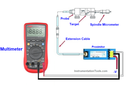
The spindle micrometer is used to check the voltage versus distance characteristics of the probe and proximitors. It is also used to calibrate thrust position.

The wobulator generates a precise vibration and keyphasor reference. The peak to peak vibration is controlled by manually operated swing arm and checked with dial indicator included in the kit. The rotating speed of the wobulator is controlled by adjusting the speed control knob.

If a probe has been permanently installed in a machine or is otherwise inaccessible, a probe with identical electrical characteristics can be substituted for calibration purposes.

A complete vibration monitoring system can be checked by applying a known mechanical input to the probes and observing the meter indication or by measuring the monitor output.

Principle

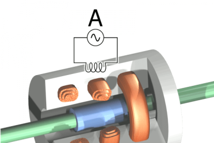
The TK-3 Calibration Instrument simulates shaft vibration and position for calibrating Bently Nevada monitors and checking the vibration probes. It verifies the operating condition of the monitor readouts as well as the condition of the proximity transducer system. A properly calibrated system ensures that the transducer inputs and the resulting monitor readings are accurate.

It verifies the operating condition of the monitor readouts as well as the condition of the proximity transducer system. A properly calibrated system means that the monitor readings and transducer inputs are accurate and both readings will be matched.

A spindle micrometer is used to check the transducer system and position monitor calibration. A probe mounting adapter provided with the TK3-2 holds the probe while the target is moved toward or away from the

probe tip in calibrated increments. The output from the Proximitor® Sensor is recorded using a voltmeter.

Vibration monitors are calibrated using the motor-driven wobble plate. A swing-arm holder is located over the wobble plate to hold the proximity probe in place. The holder and probe are adjusted to a position where the desired amount of mechanical vibration is found.

The vibration is then measured using a dial micrometer which is supplied with the unit (no oscilloscope is needed). A vibration monitor’s reading can then be compared to the known mechanical vibration signal input. The mechanical vibration signal from the TK3-2 can range from 50 to 254 µm (2 to 10 mils) peak-to-peak.

Download : Reference Manual

Don't Miss Our Updates
Be the first to get exclusive content straight to your email.
We promise not to spam you. You can unsubscribe at any time.
Invalid email address
You've successfully subscribed !
What is Turbine Supervisory Instrumentation (TSI)?
Non-contact Vibration Measurement
Determine Lifting of Shaft using Proximity Sensor
Seismic Transducers Objective Questions
Contact Vibration Measurement
Share This Article
Facebook Whatsapp Whatsapp LinkedIn Copy Link
Share
4 Comments
  • Siddhant Deputy says:
    May 16, 2017 at 3:07 pm

    you are helping a lot of people!keep up the good work sir!

    Reply
  • Mohammad ASHFAQUE alam says:
    May 17, 2017 at 6:20 pm

    nice work and your topic to help full

    Reply
  • Viky says:
    October 20, 2017 at 12:42 pm

    Thanks you are providing a great service.

    Reply
  • Juan says:
    August 18, 2021 at 4:06 am

    What’s the best way to identify if the cable is the main issue on gap voltage inconsistency?

    Reply

Leave a Reply Cancel reply

Your email address will not be published. Required fields are marked *

Stay Connected

128.3kFollowersLike
69.1kFollowersFollow
208kSubscribersSubscribe
38kFollowersFollow

Categories

Recent Comments

  • MIHARITSOA Aina Sitraka on Top Non-PLC Certification Courses for Automation Professionals
  • Vaishnavi on Free Instrumentation Course for Trainee Engineers
  • anuj kapoor on DCS Program to Maintain Draft in Furnace
  • anuj kapoor on IoT based Smart Boiler Control System with Cloud PLC and SCADA

Related Articles

Accelerometer Vibration Probe

Accelerometer Vibration Probe Principle

proximitor module

Bently Nevada Vibration System Verification Procedure

Why we use -24vdc in vibration measurement

Why we use Negative Voltage in Vibration Measurement ?

vibration probe mounting

Mechanical Vibration Switch Principle

Guide to vibration severity per ISO 10816

Importance of Vibration Measurement

hall effect speed sensor

Speed Probe Working Principle

Advantages and Disadvantages of Network Topology

Advantages & Disadvantages of Different Vibration Sensors

Vibration Monitoring System Troubleshooting

Vibration Monitoring System Step by Step Troubleshooting Guide

More Articles

Group of Induction Motors

How to Operate a Group of Induction Motors using PLC Logic?

Types of Allen Bradley PLC

Types of Allen Bradley PLC

Thermistors and Resistance Temperature Detectors (RTDs)

Thermistors and Resistance Temperature Detectors (RTDs)

Instrumentation Standards Questions & Answers

Instrumentation Standards Questions and Answers

Dual-beam non-dispersive analyzer

Dual-beam Non-dispersive Analyzer

Hook-up Diagram for Pressure Gauge

What is Instrument Hook Up Diagram ?

safety PLC programming

SIS Logic Solver

PLC Programming for Level Switches

PLC Programming using Level Switches

Follow US
All rights reserved. Reproduction in whole or in part without written permission is prohibited.
Welcome Back!

Sign in to your account

Username or Email Address
Password

Lost your password?