Inst ToolsInst ToolsInst Tools
  • Courses
  • Automation
    • PLC
    • Control System
    • Safety System
    • Communication
    • Fire & Gas System
  • Instrumentation
    • Design
    • Pressure
    • Temperature
    • Flow
    • Level
    • Vibration
    • Analyzer
    • Control Valve
    • Switch
    • Calibration
    • Erection & Commissioning
  • Interview
    • Instrumentation
    • Electrical
    • Electronics
    • Practical
  • Q&A
    • Instrumentation
    • Control System
    • Electrical
    • Electronics
    • Analog Electronics
    • Digital Electronics
    • Power Electronics
    • Microprocessor
Search
  • Books
  • Software
  • Projects
  • Process
  • Tools
  • Basics
  • Formula
  • Power Plant
  • Root Cause Analysis
  • Electrical Basics
  • Animation
  • Standards
  • 4-20 mA Course
  • Siemens PLC Course
Reading: Steps to Import PlantPAx Add-On Instructions in Studio 5000
Share
Notification Show More
Font ResizerAa
Inst ToolsInst Tools
Font ResizerAa
  • Courses
  • Design
  • PLC
  • Interview
  • Control System
Search
  • Courses
  • Automation
    • PLC
    • Control System
    • Safety System
    • Communication
    • Fire & Gas System
  • Instrumentation
    • Design
    • Pressure
    • Temperature
    • Flow
    • Level
    • Vibration
    • Analyzer
    • Control Valve
    • Switch
    • Calibration
    • Erection & Commissioning
  • Interview
    • Instrumentation
    • Electrical
    • Electronics
    • Practical
  • Q&A
    • Instrumentation
    • Control System
    • Electrical
    • Electronics
    • Analog Electronics
    • Digital Electronics
    • Power Electronics
    • Microprocessor
Follow US
All rights reserved. Reproduction in whole or in part without written permission is prohibited.
Inst Tools > Blog > Control Systems > Steps to Import PlantPAx Add-On Instructions in Studio 5000

Steps to Import PlantPAx Add-On Instructions in Studio 5000

In this article, you will learn the steps to import PlantPAx Add-On Instructions in Studio 5000 logix designer.

Last updated: July 2, 2022 11:22 am
Editorial Staff
Control Systems
No Comments
Share
3 Min Read
SHARE

PlantPAx Library consists of a set of Add-on-blocks for configuring parameters and operating analog inputs, analog outputs, digital inputs, and digital outputs.

Import Add-On Instructions in Studio 5000

We will Import all required add-on-instructions to help us create instructions for analog inputs, analog outputs, digital inputs, and digital outputs.

Step1: Open Studio 5000. Click on New Project and Select controller.
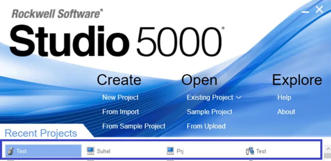
Studio 5000

If you have PLC Hardware you can choose Specific Controller from the list and type the name of the project you want and click on Next.
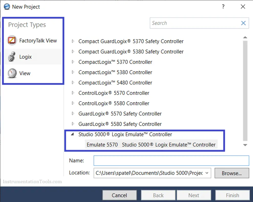
Studio 5000 Logix Emulate Controller

I have selected Emulator (Studio 5000 Logix emulate)

Step 2: Right Click on Add on Instructions and click on Import add on Instructions.

For Analog Inputs, Select all P-AIN Add-On-Instructions as per requirements as shown below.
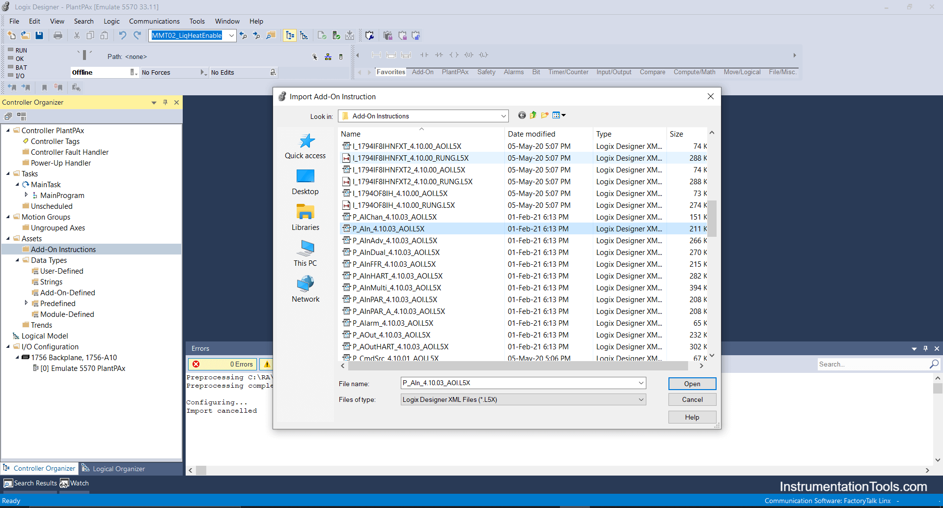
Select P-AIN Add-On-Instructions

P-AIN- It states Analog Input block as shown below.
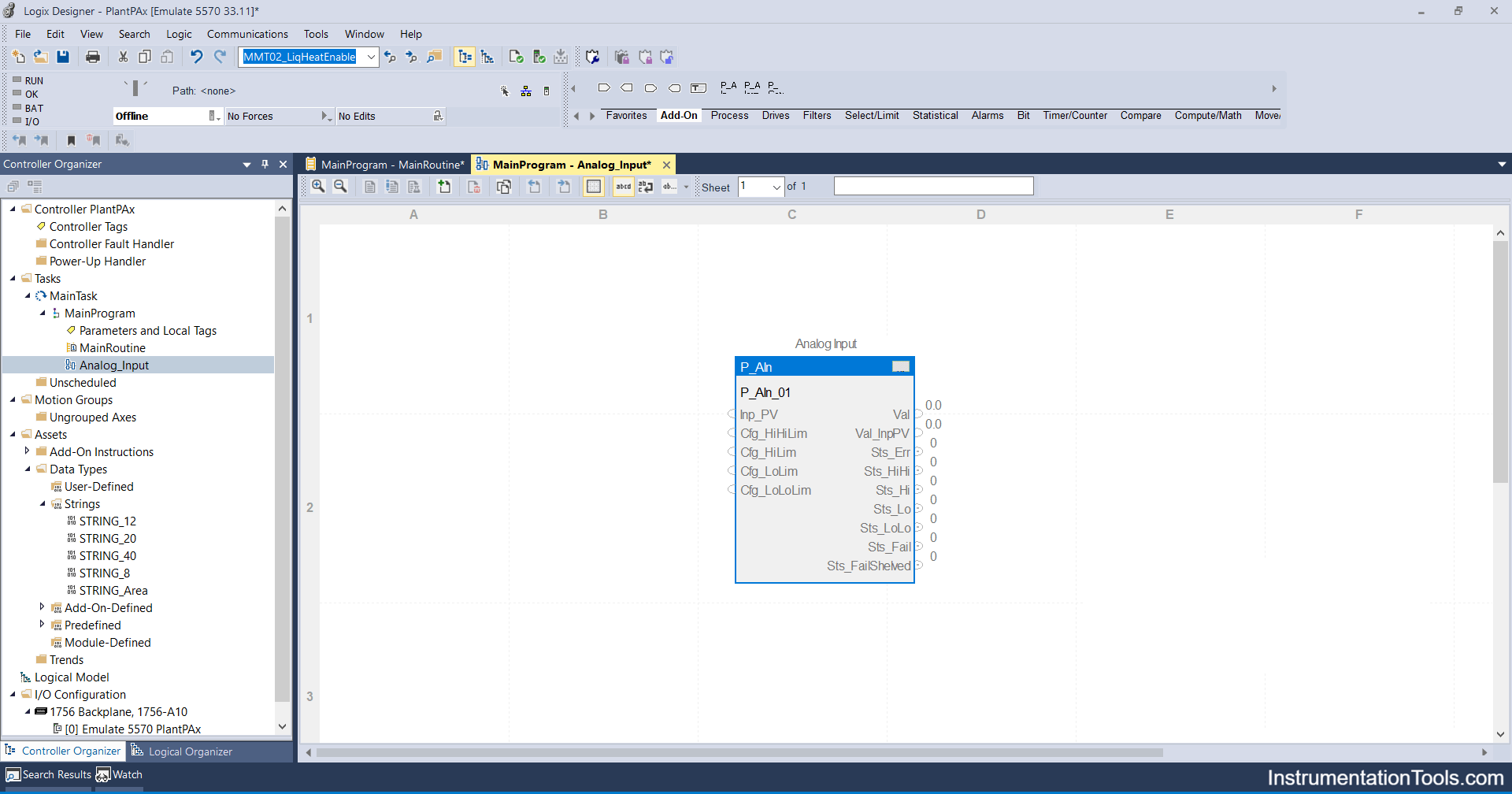
PlantPax Analog Input Block

Below are the Parameters, according to requirements you can choose.
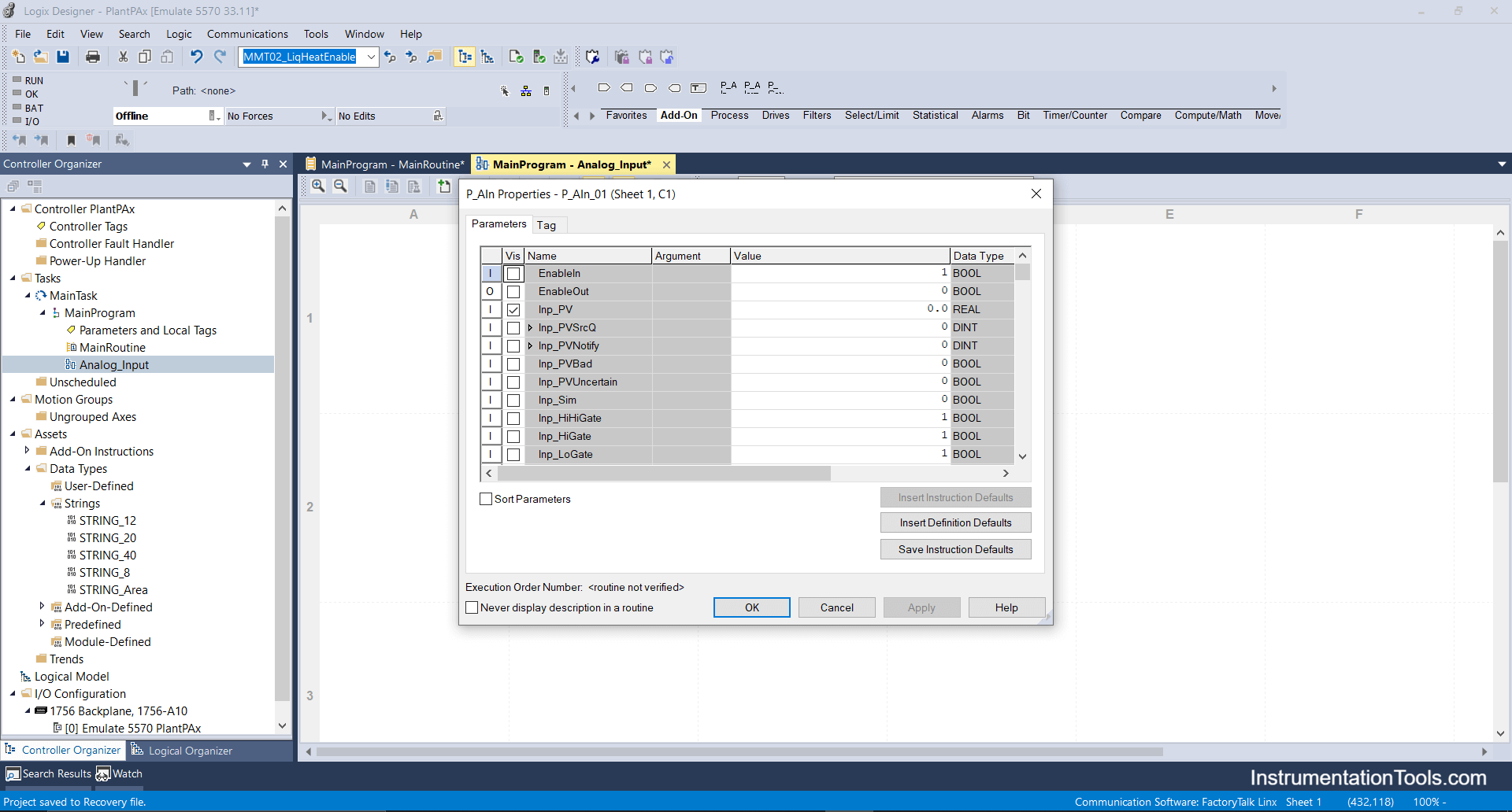
Steps to Import PlantPAx Add-On Instructions in Studio 5000

Step 3: Import all required analog input add-on instructions similarly.
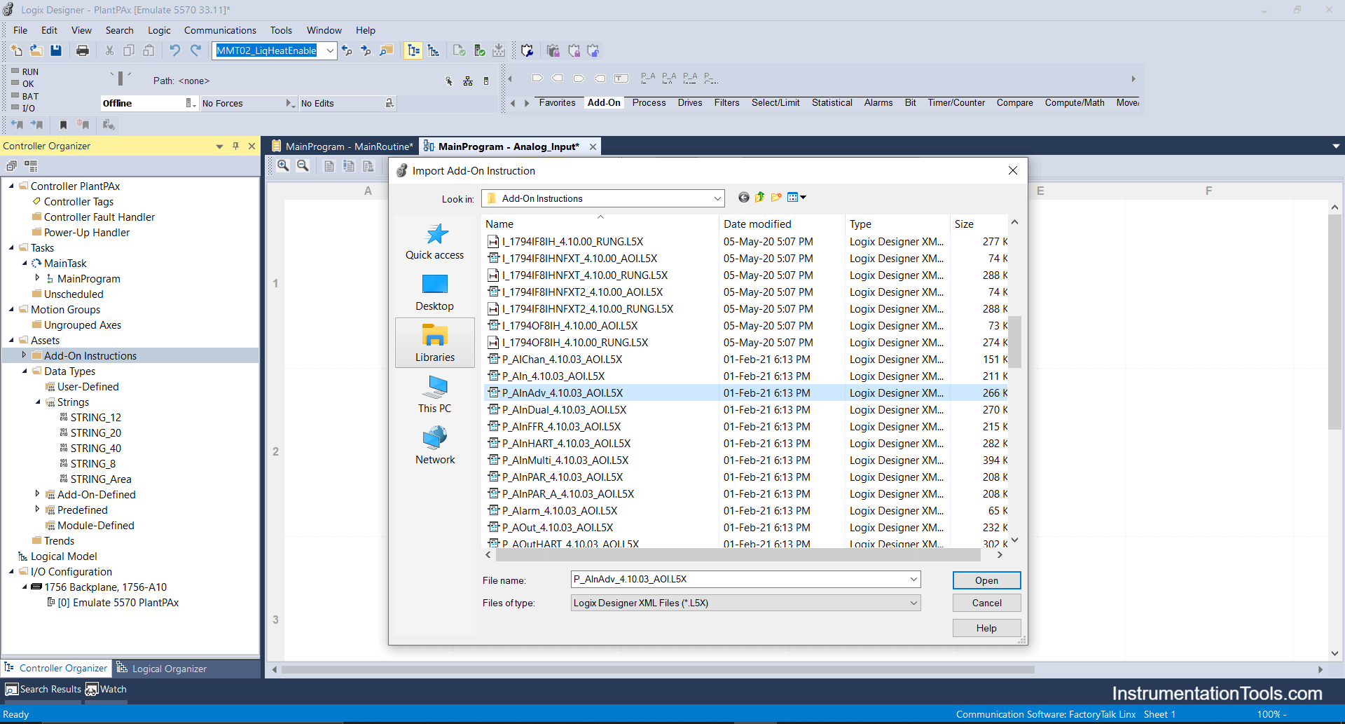
Import analog input add on instructions in studio 5000

Please note below add-on-instruction will work on the Functional block diagram routine only as it indicates the FBD symbol.

FBD symbol

You will see some add-on instructions in the list that will work on the Ladder diagram only.

Ladder Diagram add-on instructions list

Step 4: For analog outputs, for the control valve, I will be using the P_PIDE add-on block as it has better functionality for tuning and better scalable parameters.
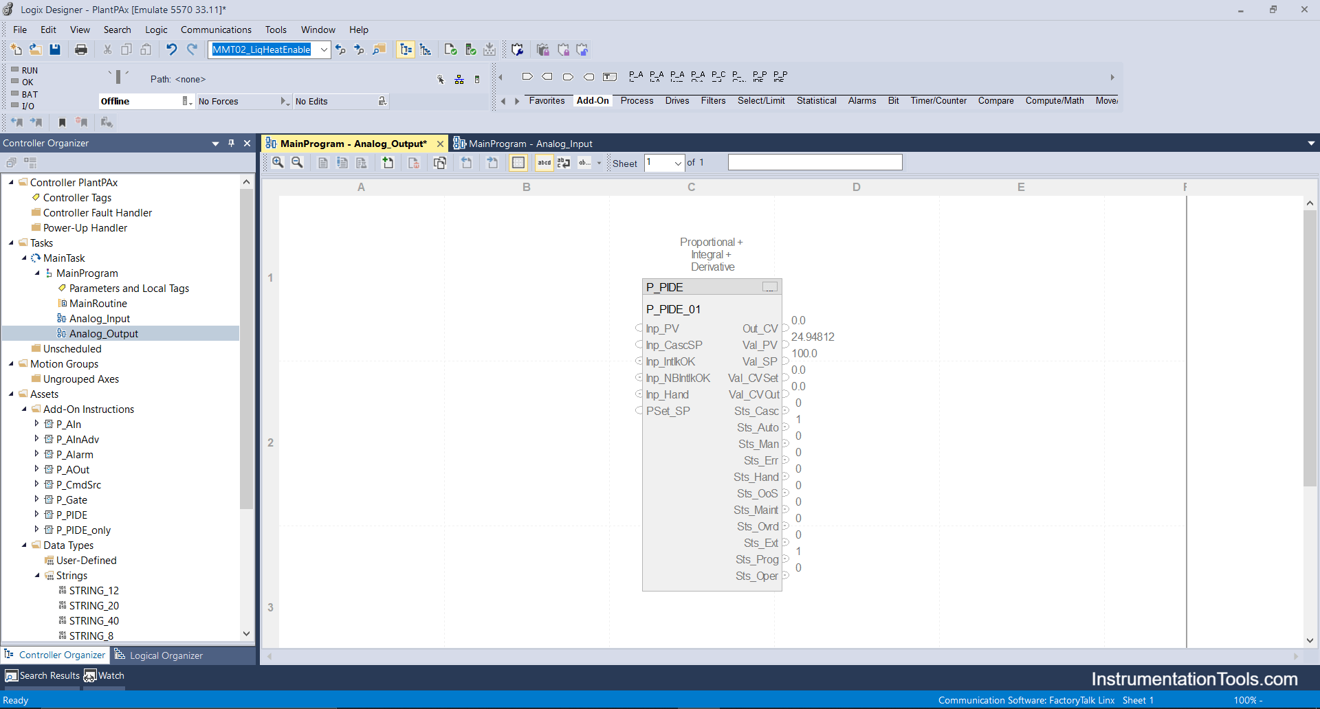
P_PIDE add-on block

Step 5: Now I will import the Digital input add-on block eg: it can be used for limit switches, relays, etc. as per your availability and requirements of parameters you can select the checkboxes.
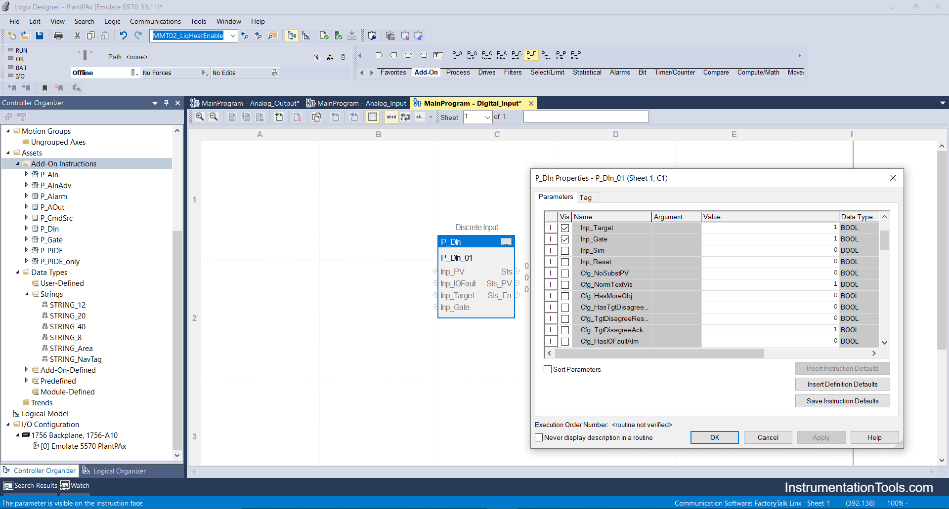
Digital input add-on block in PlantPax

Step 6: Next I will import Digital _Output add-on instructions, this can be used for configuring and operating On-Off valves, dampers, electrical motors, indicators and alarm bells.

a. Digital Output block add-on for Solenoid On-Off valve.
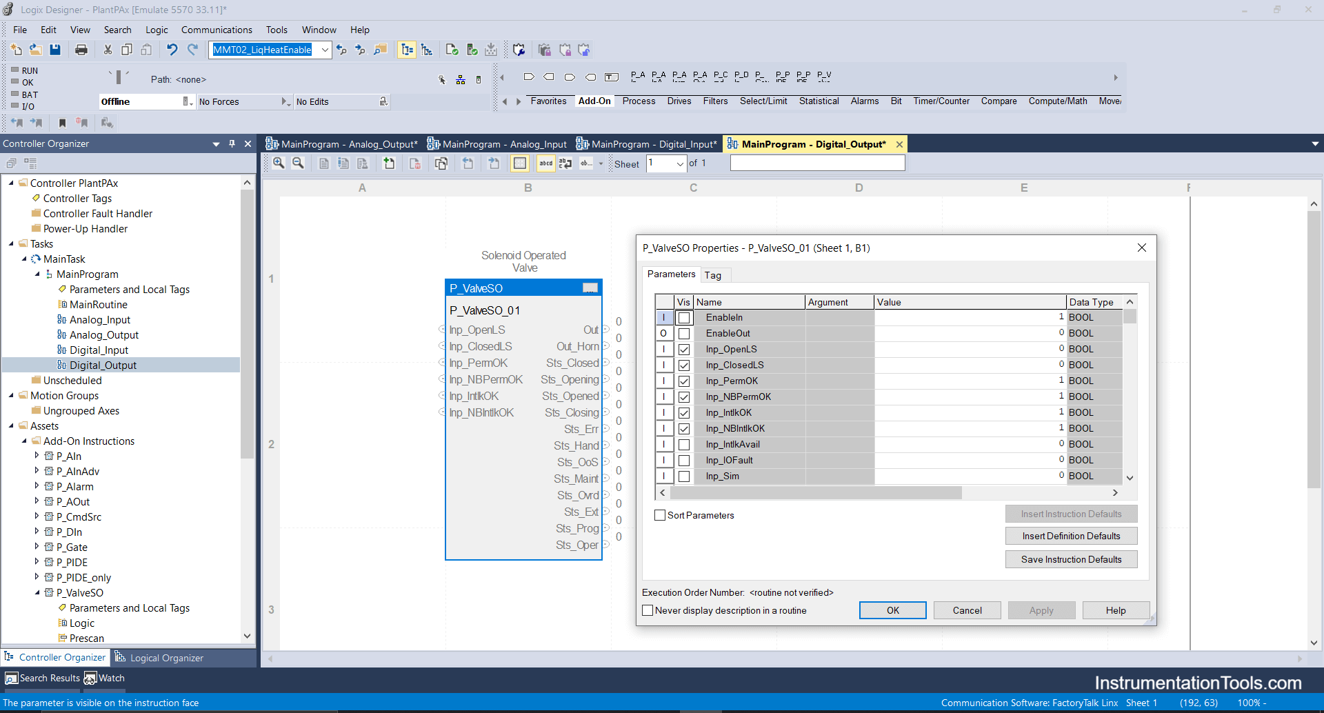
Digital Output block add-on for Solenoid On-Off valve

b. Digital output block add-on for Variable speed drive.
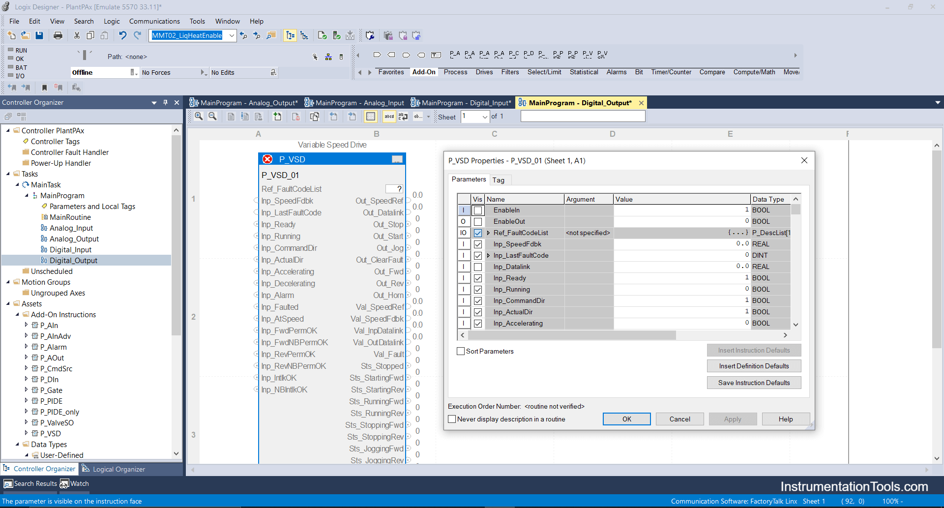
Digital output block add-on for Variable speed drive

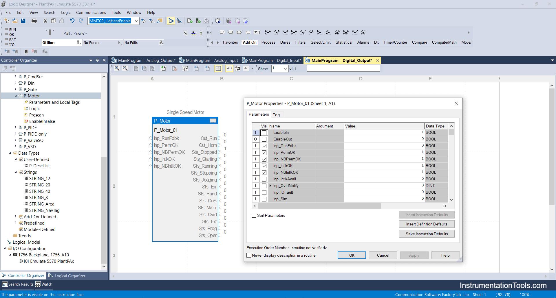
c. Digital Output block for Motor

Digital Output block for Motor in Logix Designer

Step 7: Now I will be importing the most important and frequently used add-on block called “Interlock” which can be used anywhere to provide interlock to any device for the legitimate process.
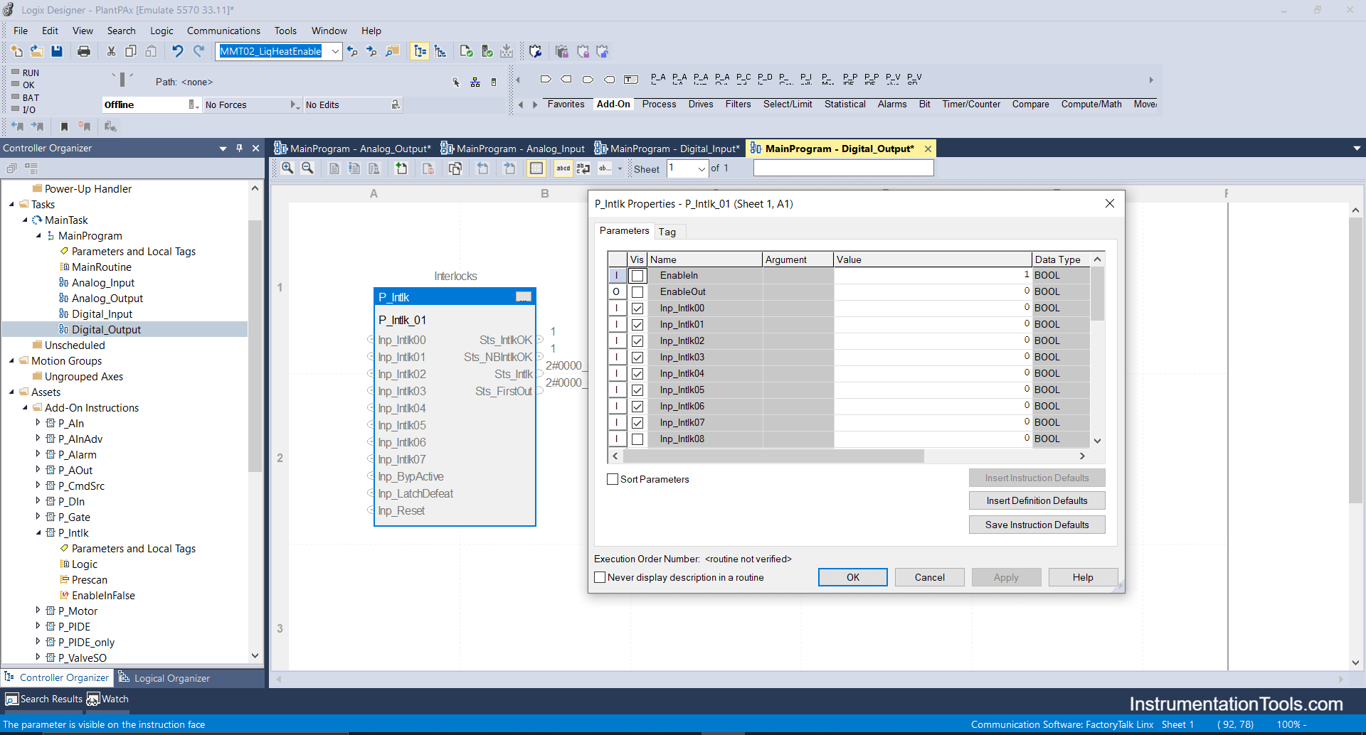
Interlock Function Block in Studio 5000

Interlock block has a 16-bit array i.e you can configure 16 interlocks for a valve or motor or any digital output devices.

If you liked this article, then please subscribe to our YouTube Channel for Electrical, Electronics, Instrumentation, PLC, and SCADA video tutorials.

You can also follow us on Facebook and Twitter to receive daily updates.

Read Next:

  • Import PlantPAx Library
  • DCS Technical Evaluation
  • Download PlantPAx Library
  • Condensing Turbine System
  • Cloud PLC and SCADA System
Don't Miss Our Updates
Be the first to get exclusive content straight to your email.
We promise not to spam you. You can unsubscribe at any time.
Invalid email address
You've successfully subscribed !

Continue Reading

Derivative Controller Principle
Best Way to Build Troubleshooting Mindset for Automation Engineer
Process Dynamics and PID Controller Tuning
Interview Questions on PID Controllers
Safety in Automation Systems
Learn about PLC, DCS, RTU, SCADA, and PAC
Share This Article
Facebook Whatsapp Whatsapp LinkedIn Copy Link
Share
Leave a Comment

Leave a Reply Cancel reply

Your email address will not be published. Required fields are marked *

Stay Connected

128.3kFollowersLike
69.1kFollowersFollow
208kSubscribersSubscribe
38kFollowersFollow

Categories

Explore More

How to Analyze PID Controller Actions
Why 4-20 mA Current Signal is used instead of Voltage Signal?
Overview of Industrial Control Systems
Loop-powered 4-20 mA Transmitter Circuit Voltage drop
How to Implement Ratio Control in this System?
Difference Between Batch Process and Continuous Process
Motor Control Signal Interface
What is a Control Panel and its types?

Keep Learning

Grounding Components

Selection of Components Used In Electrical Earthing or Grounding

Closed Loop Control System

Types of Control Systems

Integral (Reset) Control Theory

Fundamental Motion Control Commands

Fundamental Motion Control Commands

What is Profibus

All About Fieldbus Protocols

PID Loop Tuning

PID Controller Loop Tuning Questions and Answers – Part 1

Remote User Authentication

Security of Industrial Automation Systems

Distributed Control System & Motor Control Center Interface Philosophy

Distributed Control System & Motor Control Center Interface Philosophy

Learn More

Advantages & Disadvantages of Oil Circuit Breakers

Advantages & Disadvantages of Oil Circuit Breakers

Power Electronics Objective Questions

Thyristors Mock Test

Transistor as Amplifier

Transistor as Amplifier

Advantages & Disadvantages of CNC Milling

What are the Advantages & Disadvantages of CNC Milling?

Instrument Skid

What is an Instrument Skid? – Example of Metering Skid

Encoder Questions

Encoder Multiple Choice Questions

5-valve manifold

Pressure Transmitter Vent fittings

Portable Gas Detectors Calibration Procedure

Portable Gas Detectors Calibration Procedure

Follow US
All rights reserved. Reproduction in whole or in part without written permission is prohibited.
Welcome Back!

Sign in to your account

Username or Email Address
Password

Lost your password?