Inst ToolsInst ToolsInst Tools
  • Courses
  • Automation
    • PLC
    • Control System
    • Safety System
    • Communication
    • Fire & Gas System
  • Instrumentation
    • Design
    • Pressure
    • Temperature
    • Flow
    • Level
    • Vibration
    • Analyzer
    • Control Valve
    • Switch
    • Calibration
    • Erection & Commissioning
  • Interview
    • Instrumentation
    • Electrical
    • Electronics
    • Practical
  • Q&A
    • Instrumentation
    • Control System
    • Electrical
    • Electronics
    • Analog Electronics
    • Digital Electronics
    • Power Electronics
    • Microprocessor
  • Request
Search
  • Books
  • Software
  • Projects
  • Process
  • Tools
  • Basics
  • Formula
  • Power Plant
  • Root Cause Analysis
  • Electrical Basics
  • Animation
  • Standards
  • 4-20 mA Course
  • Siemens PLC Course
Reading: What is Open Systems Interconnection?
Share
Notification Show More
Font ResizerAa
Inst ToolsInst Tools
Font ResizerAa
  • Courses
  • Design
  • PLC
  • Interview
  • Control System
Search
  • Courses
  • Automation
    • PLC
    • Control System
    • Safety System
    • Communication
    • Fire & Gas System
  • Instrumentation
    • Design
    • Pressure
    • Temperature
    • Flow
    • Level
    • Vibration
    • Analyzer
    • Control Valve
    • Switch
    • Calibration
    • Erection & Commissioning
  • Interview
    • Instrumentation
    • Electrical
    • Electronics
    • Practical
  • Q&A
    • Instrumentation
    • Control System
    • Electrical
    • Electronics
    • Analog Electronics
    • Digital Electronics
    • Power Electronics
    • Microprocessor
  • Request
Follow US
All rights reserved. Reproduction in whole or in part without written permission is prohibited.
Inst Tools > Blog > Control Systems > What is Open Systems Interconnection?

What is Open Systems Interconnection?

The purpose of Open Systems Interconnection is to standardize network architecture and encourage vendors to develop network equipment that would avoid proprietary design.

Last updated: September 28, 2022 2:38 pm
R Jagan Mohan Rao
Control Systems
No Comments
Share
5 Min Read
SHARE

The purpose of Open Systems Interconnection (OSI) is to standardize network architecture and encourage vendors to develop network equipment that would avoid proprietary design.

Contents
Open Systems InterconnectionFunctions of each OSI LayerApplication LayerPresentation LayerSession LayerTransport LayerNetwork LayerData Link LayerPhysical LayerAdvantagesDisadvantages

International Standards organization (ISO) in 1974 produced an open system interconnection reference model.

It allows any computer system anywhere in the world to communicate with any other, as long as both obey OSI protocol standards.

OSI has codified in the reference model referred to as the OSI/RM. It is an abstract description of inter-process communications.

It defines types of objects that are used to describe an open system, the general relations among these types of objects, and general constraints on these types of object relations.

A seven-layer OSI model is used to represent the OSI/RM, its overall architecture, the services provided, the functions necessary to be performed, and peer protocols needed for achieving inter-process communication.

Open Systems Interconnection

Open Systems Interconnection

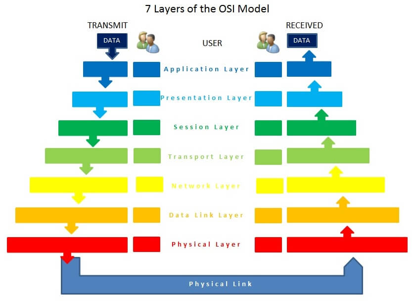
Image Courtesy: Wikimedia Commons

To assure an end to end systems interoperability, adherence to the OSI/RM is not sufficient. It is only achieved when full compliance with the OSI peer protocol is satisfied.

The services provided by the seven layers of the OSI/RM can be divided into three main regions, as shown below.

Network Utilities-layers 7,6, and 5.

Host to host transport and internet working – Layers 4, and 3.

Sub-network transmission (Local area and wide area networks) – Layers 3,2,1 and Media 0. Layers 3,2,1 and Media 0.

Functions of each OSI Layer

Application Layer

Layer 7 provides interfaces for applications to access network services such as file sharing, message handling, and data access.

It also handles error recovery for applications, as desired.

Presentation Layer

The presentation layer at level 6, handles data formatting and translation. For outgoing messages, the presentation layer converts data into a format specified by the Application layer, if necessary; for incoming messages, it reverses the conversion if required by the receiving application.

In short, Layer 6 presents the data in a suitable to the application layer.

The presentation layer engages protocol conversion, data encryption, decryption, data compression, decompression, data representation incompatibilities between OSI, and graphic commands.

Session Layer

Layer 5, the session layer permits two computers to hold ongoing communications-called a session – across a network so applications on either end of the session can swap or exchange data as long as the session lasts.

Transport Layer

The transport layer is (Layer 4) manages data transfer from one application to another across a network.

It breaks long data streams into smaller blocks called “Segments”.

Network Layer

The network layer, below the Transport layer, is responsible for routing the packet based on its logical address.

It moves packets of data from the source to the destination and across the networks if necessary.

Data Link Layer

Layer 2 the data link layer, works with frames and is the mediator between the Network layer and Physical layer.

It defines how computers access the network medium – also called Media Access Control (MAC), which is why the MAC address is defined at this layer.

Physical Layer

The activity of Layer 1 is to convert bits into signals for outgoing messages and signals into bits for incoming messages.

The type of signal generated depends upon the medium.

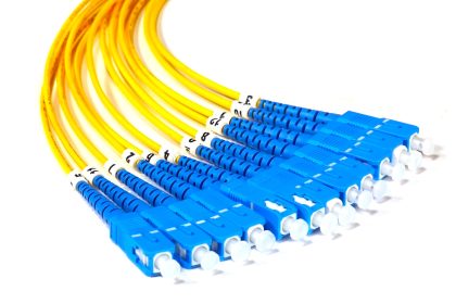
For example, wire media, such as twisted pair cable, use electrical pulses, fiber optic media use pulses of light, and wireless media uses radio waves.

Advantages

  • OSI furnishes the interoperability of diversified communication systems with standard communication and transmission architecture, layers, and protocols.
  • OSI model is an architecture to specify computer network functions in a clear and compatible way.
  • Since protocols are hidden, any protocols can be implemented in this model.

Disadvantages

  • It does not define any particular protocol.
  • OSI model is relatively less reliable compared with TCP/IP.

Read Next:

  • History of Instrument Signals
  • Compare Fieldbus & 4-20mA
  • Why 4-20 mA Popular?
  • What is Live Zero in 4-20 mA?
  • Loop Checking of Transmitters
Don't Miss Our Updates
Be the first to get exclusive content straight to your email.
We promise not to spam you. You can unsubscribe at any time.
Invalid email address
You've successfully subscribed !

Continue Reading

Identify Faults in PID Control Loop
Types of SCADA System Architecture
Overview of Industrial Control Systems
Readings Mismatch between Field & Control Room ? Why
Basics of Grounding
Relay Operation, Types, Symbols & Characteristics
Share This Article
Facebook Whatsapp Whatsapp LinkedIn Copy Link
Share
Leave a Comment

Leave a Reply Cancel reply

Your email address will not be published. Required fields are marked *

Stay Connected

128.3kFollowersLike
69.1kFollowersFollow
210kSubscribersSubscribe
38kFollowersFollow

Categories

Explore More

Hardware Troubleshooting Steps for PLC Automation Systems
What is WHCP?
Instrumentation Engineer in Process Plant Project
Understanding Emergency Shutdown Button Installation (ESD)
Most Asked Questions on SCADA with Answers
Basics of 4 to 20 mA analog Signals
Difference between Process shutdown and Emergency Shutdown
How to Choose the Right Industrial Automation Solution?

Keep Learning

Tips for Reducing the Noise Signals

Tips for Reducing the Noise Signals

Simple Loop with Local Indication

Instrument Loop Test Requirements and Operation Procedures

Earthing Calculations

Electrical Earthing Calculations

Instrumentation and Control (I&C) Design

Instrumentation and Control (I&C) Design

Types of Failures in Industrial Automation Systems

Types of Failures in Industrial Automation Systems

How Twisted Wire Cables Eliminates Noise Voltage

Inductive Coupling Effects

Loop Splitter Theory of Operation

4-20 mA Loop Splitter

DCS Program to Maintain Draft in Furnace

DCS Program to Maintain Draft in Furnace

Learn More

Absolute and Gauge Pressure

Difference Between Absolute and Gauge Pressure

Automobile Engineering Projects

220+ Automobile Engineering Projects

Networked SCADA Architecture

Types of SCADA System Architecture

Difference Between Modbus TCP IP and Profinet

Difference Between Modbus TCP IP and Profinet

Importance of Hysteresis Loop

PN Junction Questions & Answers

Measurement and Instrumentation Objective Questions – Part 5

Functional Safety Terms in Industrial Automation

Functional Safety Terminology in Industrial Automation

Split Range in Foundation Fieldbus

Foundation Fieldbus Split Range Valves

Menu

  • About
  • Privacy Policy
  • Copyright

Quick Links

  • Learn PLC
  • Helping Hand
  • Part Time Job

YouTube Subscribe

Follow US
All rights reserved. Reproduction in whole or in part without written permission is prohibited.
Welcome Back!

Sign in to your account

Username or Email Address
Password

Lost your password?