Inst ToolsInst ToolsInst Tools
  • Ask
  • Courses
  • Videos
  • Q & A
    • Interview
      • Instrumentation
      • Electronics
      • Electrical
      • Practical Questions
    • MCQ
      • Instrumentation MCQ
      • Electrical MCQ
      • Electronics MCQ
      • Control Systems MCQ
      • Analog Electronics MCQ
      • Digital Electronics MCQ
      • Power Electronics MCQ
      • Microprocessor MCQ
      • Multiple Choice Questions
  • EE
    • Electronics
      • Electronics Q & A
      • Electronic Basics
      • Electronic Devices & Circuits
      • Electronics Animation
      • Digital Electronics
    • Electrical
      • Electrical Basics
      • Electrical Q & A
      • Power Electronics
      • Electrical Machines
      • Electrical Animation
      • Power Systems
      • Switchgear & Protection
      • Transmission & Distribution
  • Measure
    • Control Valves
    • Calibration
    • Temperature
    • Pressure
    • Flow
    • Level
    • Analyzers
    • Switches
    • Vibration
    • Solenoid Valve
  • Control
    • PLC Tutorials
    • Control Systems
    • Safety Instrumented System (SIS)
    • Communication
    • Fire & Gas System
  • More
    • Design
    • Tools
    • Animation
    • Basics
    • Formulas
    • Standards
    • TextBooks
    • Common
    • Software
    • Excel Tools
    • Erection & Commissioning
    • Process Fundamentals
    • Videos
    • Books
Search
All rights reserved. Reproduction in whole or in part without written permission is prohibited.
Reading: How to Read an Electrical Wiring Diagram?
Share
Notification Show More
Font ResizerAa
Inst ToolsInst Tools
Font ResizerAa
  • Courses
  • PLC Tutorials
  • Control Systems
Search
  • Ask
  • Courses
  • Videos
  • Q & A
    • Interview
    • MCQ
  • EE
    • Electronics
    • Electrical
  • Measure
    • Control Valves
    • Calibration
    • Temperature
    • Pressure
    • Flow
    • Level
    • Analyzers
    • Switches
    • Vibration
    • Solenoid Valve
  • Control
    • PLC Tutorials
    • Control Systems
    • Safety Instrumented System (SIS)
    • Communication
    • Fire & Gas System
  • More
    • Design
    • Tools
    • Animation
    • Basics
    • Formulas
    • Standards
    • TextBooks
    • Common
    • Software
    • Excel Tools
    • Erection & Commissioning
    • Process Fundamentals
    • Videos
    • Books
Follow US
All rights reserved. Reproduction in whole or in part without written permission is prohibited.
Inst Tools > Blog > PLC Tutorials > How to Read an Electrical Wiring Diagram?

How to Read an Electrical Wiring Diagram?

In this article, we will learn how to read an electrical wiring diagram, how to understand electrical engineering drawings.

Last updated: October 17, 2023 1:55 pm
Hussien Ghareb
PLC Tutorials
2 Comments
Share
7 Min Read
SHARE

Did you ever ask yourself, how could the Automation Engineers go through the Electric Panels wiring?

Contents
The Function of Electrical Wiring DiagramsHow to Read an Electrical Wiring Diagram?Legend PageDirection of the DrawingDashed lineConnecting the wiring togetherMarshalling TerminalsSizing of the cables and wiring dataBest Programs for Drawing an Electrical Wiring

There are a lot of wires are going up and down how could they know every path for each wire without making any effort.

Today we will discuss a very important topic that would help you to be familiar with the different electric wiring diagrams, and it will help you to not stuck with any Electric panel.

How to Read an Electrical Wiring Diagram
Figure 1

The Function of Electrical Wiring Diagrams

First of all, you have to ask yourself “why am I supposed to do that?” and the answer stays for the amount of Automation that you have.

In most plants you do not have just one or two motors to control, you have many and many motors, sensors, and control circuits to look for.

So, it is impossible to have all of these wires just in your mind, we need some Global Standards for drawing these types of Electrical panels in a good way that allows for any person to understand it simply.

That is just what an electrical wiring diagram can do, it does not depend on your language or your region, it is (kind of) a unified method to describe and present the electric wiring of any panel.

Note

There are little differences between some electrical wiring diagrams, that depends on some factors like the units, company, software, and also the region, but in general, if you could understand the wiring diagrams you will be able to deal with any standard.

Just you need some time at first to be familiar with any wiring diagram.

How to Read an Electrical Wiring Diagram?

We discussed below how to read an basic electrical wiring diagram.

Legend Page

The first thing that you have to care about is the “Legend” page, this page is attached with every wiring diagram and it describes every symbol in the whole wiring, as we can see in Fig (2).

Electrical wiring diagrams Legend
Figure 2

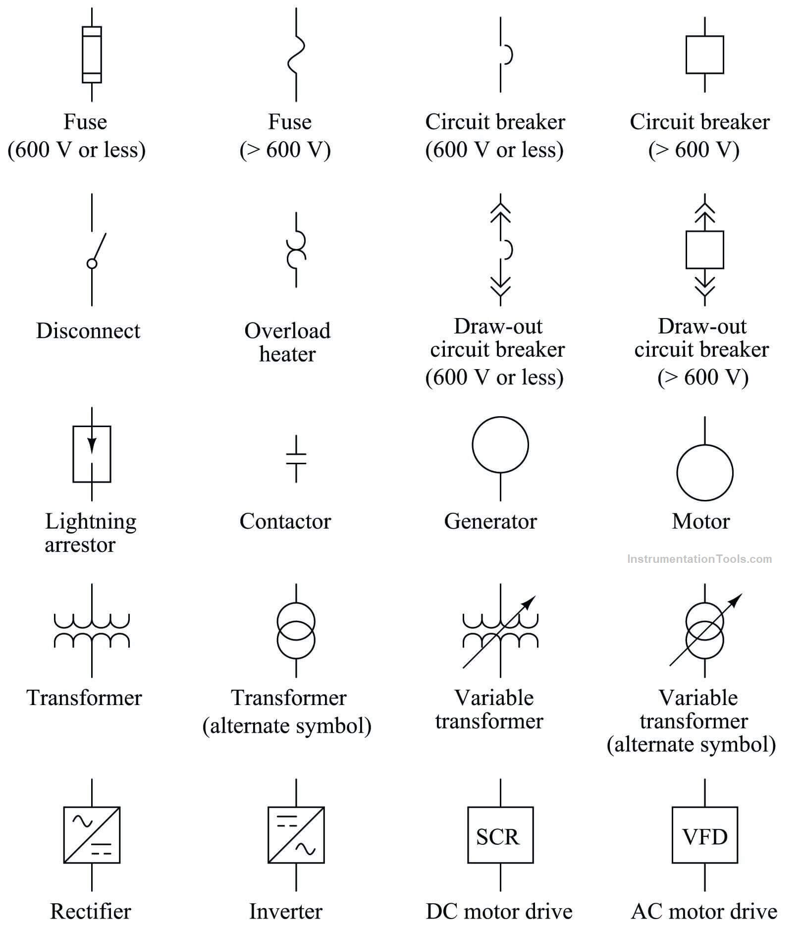
As we said before you might find some changes between the creators of the wiring diagrams so this page is made especially for each wiring to facilitate and ease the understanding and execution of the wiring.

Direction of the Drawing

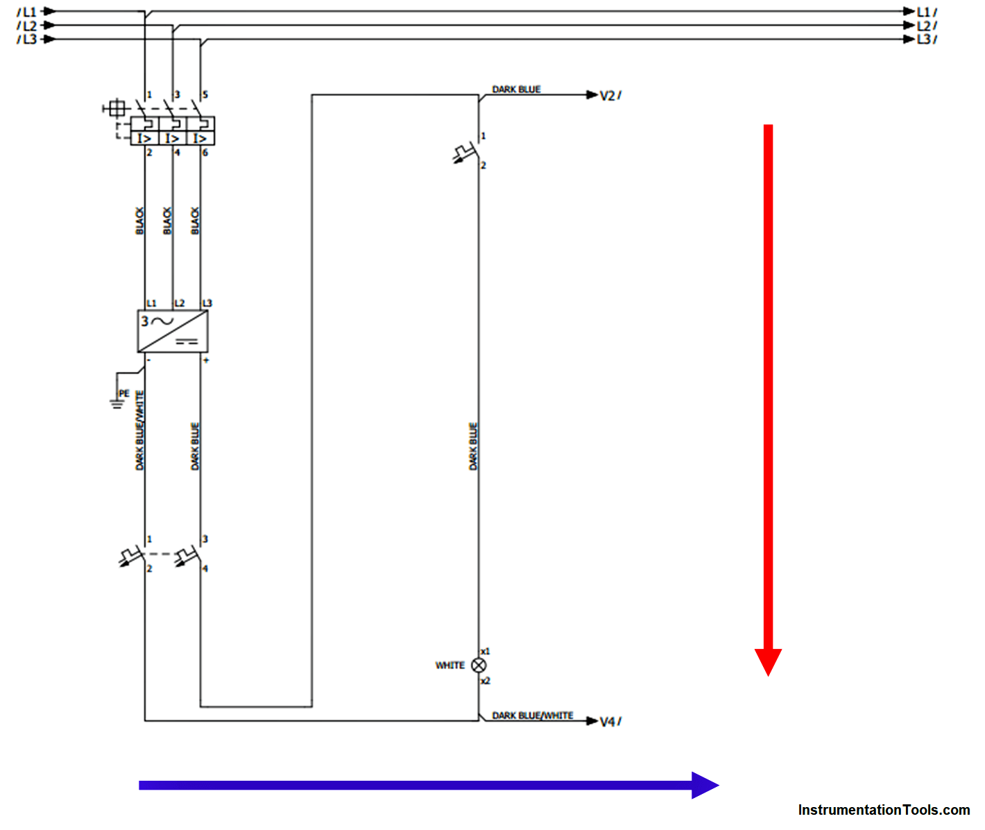
The common direction to draw a wiring diagram is from UP to DOWN and from LEFT to RIGHT.

Notice that you might see some wiring diagrams are drawn with other directions but the common directions would still as we said before.

Direction of the Electrical drawing
Figure 3

Dashed line

You have to know the difference between the lines in the drawing.

As you can see in the next figure the solid lines represent the wires between the devices in the control panel.

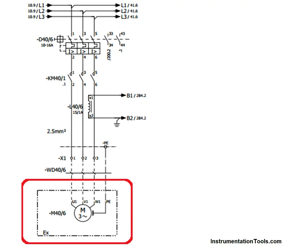
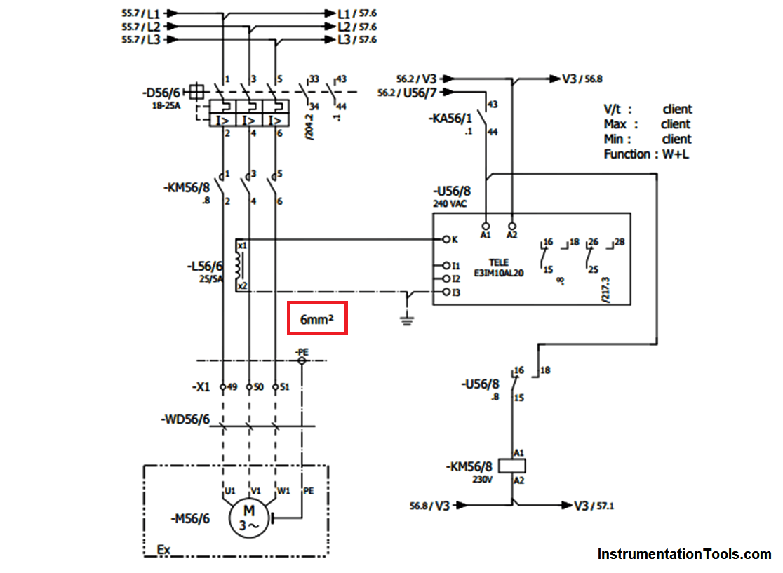
The dashed line at Fig (4) (and in all diagrams) represent that this part of the drawing is out of the panel which it means this part (motor) is not in the panel it is in the field.

How to Read Electrical Schematics
Figure 4

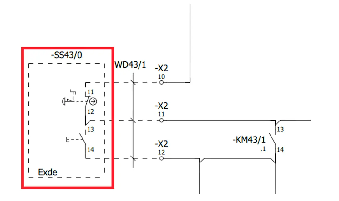
And the same for the Start Stop push buttons that are shown in Fig (5).

Start Stop push buttons Electrical Circuit
Figure 5

Connecting the wiring together

You have to know that all of the wiring papers are attached together to build a single panel.

So, you might find some common wires in all papers of the wiring.

These wires are connected together in the wiring papers by numbers that refers to the location of the intake and outtake of the wiring.

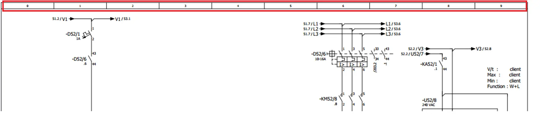
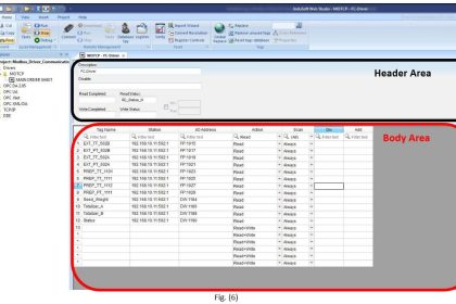
As you can see Fig (6) the wiring papers are divided into 10 sections and each section has its own number from 0 to 9.

Electrical wiring papers
Figure 6

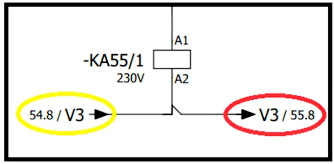
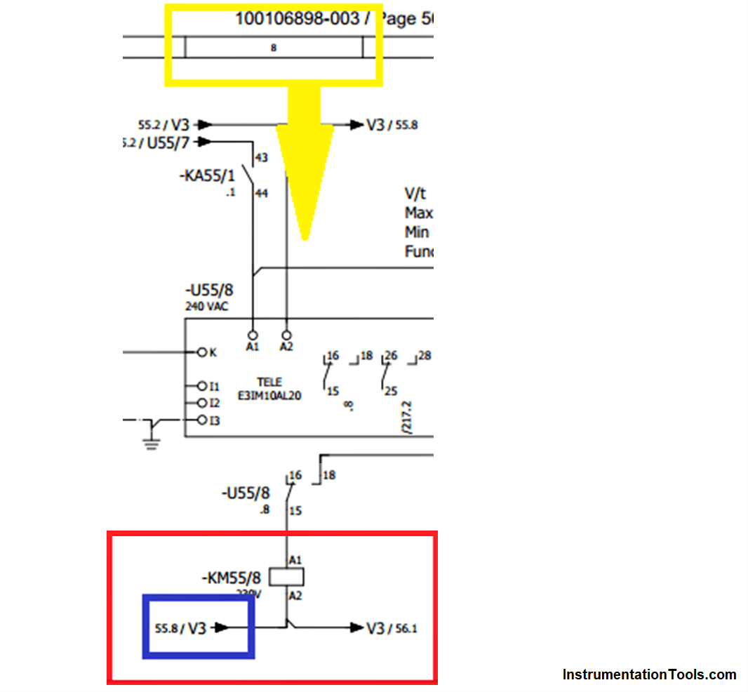
We used these sections and number of pages to allocate the end and the beginning of wires as we can see in Fig (7), the wire V3 is coming from page No. 54 section (8) and is going to page No. 55 section (8).

Location of Electrical Wire Label
Figure 7

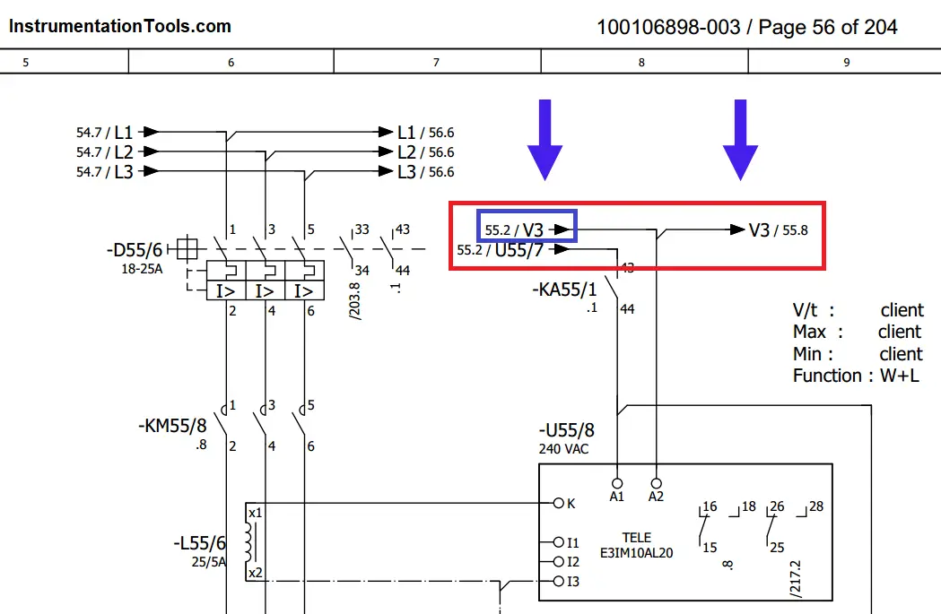
So if we went to page No. 55 section 8 as shown in Fig (8) we will find that V3 is coming from page No. 55 section 2 “which is the location of the wire at Fig (7)” and it continues its path to page No. 55 section 8 as we can see in Fig (9).

Understanding Electrical Drawings
Figure 8
Electrical Wiring Diagrams Explained
Figure 9

Marshalling Terminals

As we can see in the previous figures the panel is connected with the outside field via Marshalling terminals.

Each group of these terminals is labeled with (X1, X2, X3, ……) and each block of terminals could have about from 10 to 70 terminals.

Marshalling terminals
Figure 10

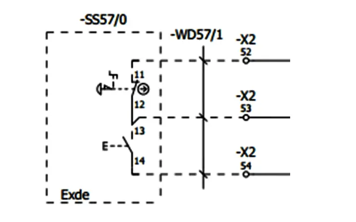
As we can see in figure (10) the start-stop push buttons that in the field is connected with the control panel via terminal block X2 at terminal No. (52, 53, 54).

Sizing of the cables and wiring data

You might see also in some wiring diagrams (not all of them) the sizing of power cables as you could see in figure (11) the size of the cable that is connected to the motor is 6mm2.

Study Electrical Diagrams and Schematics
Figure 11

Best Programs for Drawing an Electrical Wiring

If you are interested about designing Electrical wiring diagrams here is some of drawing software that might help you:

  • AutoCAD Electrical
  • ETAP
  • Smart Draw
  • EPLAN Electric

If you liked this article, then please subscribe to our YouTube Channel for PLC and SCADA video tutorials.

You can also follow us on Facebook and Twitter to receive daily updates.

Read Next:

  • Advanced Process Control
  • Power Factor Controller (PFC)
  • Building Management System
  • PLC Hardware Troubleshooting
  • Instrumentation Symbols Legend
Don't Miss Our Updates
Be the first to get exclusive content straight to your email.
We promise not to spam you. You can unsubscribe at any time.
Invalid email address
You've successfully subscribed !
Basic Pumping System Application Used in Industrial Automation
What is 21 CFR in SCADA and HMI Systems?
Siemens PLC programming: BCD, Integer, Double Integer, Real
How to Download GX Works? Mitsubishi PLC Software
Electrical Switches Principle & Types
Share This Article
Facebook Whatsapp Whatsapp LinkedIn Copy Link
Share
2 Comments
  • Mark Rama says:
    June 15, 2022 at 1:02 pm

    This is a new information about the above subject Articles in Electrical engineering. Very interesting article. Thx

    Reply
  • Abdullahi Isak says:
    December 12, 2022 at 2:53 pm

    Thank you very much, it was very helpful

    Reply

Leave a Reply Cancel reply

Your email address will not be published. Required fields are marked *

Stay Connected

128.3kFollowersLike
69.1kFollowersFollow
208kSubscribersSubscribe
38kFollowersFollow

Categories

Recent Comments

  • Guifty Shimica on Top Non-PLC Certification Courses for Automation Professionals
  • Guifty Shimica on Top Non-PLC Certification Courses for Automation Professionals
  • MIHARITSOA Aina Sitraka on Top Non-PLC Certification Courses for Automation Professionals
  • Vaishnavi on Free Instrumentation Course for Trainee Engineers

Related Articles

PLC program to control pump

Troubleshooting PLC Permissive Inputs

Comparator used in Siemens S7-1200 PLC.

Siemens PLC Comparator Logic

Marshalling Panel

What is Marshalling Cabinet?

Set the S5 timer value by a memory word

Set the S5 Timer Value by a Memory Word

Shutdown Motors in Timed Operation PLC Program

Shutdown Motors in Timed Operation PLC Program

Actuator Sensor Interface (ASi) Protocol in PLC

Actuator Sensor Interface (ASi) Protocol in PLC

Communicate between the PLC program and HMI program

Design a Program Using Studio 5000 and FactoryTalk View Studio

Digital Output Card With Relay and Wet Contact

Wiring Diagrams of PLC and DCS Systems – DI, DO, AI, AO

More Articles

Magnetic Tape Recorders Objective Questions

Magnetic Tape Recorders Objective Questions

Calibrate Eddy Current Conductivity Instrument

How to Calibrate the Eddy Current Conductivity Meter?

Single Line Diagram of UPS System

UPS Selection Factors for a Control System

Determine Calibration Range of Pneumatic Pressure Transmitter

Determine Calibration Range of Pneumatic Pressure Transmitter

How to Test a Battery using Multimeter

How to Test a Battery using a Multimeter?

How a PLC communicates with Transmitters

How PLC Reads the Data from Field Transmitters

TIA Portal Options

How to Troubleshoot Siemens PLC Programs?

CNC Milling versus CNC Turning

CNC Milling versus CNC Turning – Which is the Best Option?

Follow US
All rights reserved. Reproduction in whole or in part without written permission is prohibited.
Welcome Back!

Sign in to your account

Username or Email Address
Password

Lost your password?