Inst ToolsInst ToolsInst Tools
  • Courses
  • Automation
    • PLC
    • Control System
    • Safety System
    • Communication
    • Fire & Gas System
  • Instrumentation
    • Design
    • Pressure
    • Temperature
    • Flow
    • Level
    • Vibration
    • Analyzer
    • Control Valve
    • Switch
    • Calibration
    • Erection & Commissioning
  • Interview
    • Instrumentation
    • Electrical
    • Electronics
    • Practical
  • Q&A
    • Instrumentation
    • Control System
    • Electrical
    • Electronics
    • Analog Electronics
    • Digital Electronics
    • Power Electronics
    • Microprocessor
  • Request
Search
  • Books
  • Software
  • Projects
  • Process
  • Tools
  • Basics
  • Formula
  • Power Plant
  • Root Cause Analysis
  • Electrical Basics
  • Animation
  • Standards
  • 4-20 mA Course
  • Siemens PLC Course
Reading: How to Identify the Transistor Terminals
Share
Notification Show More
Font ResizerAa
Inst ToolsInst Tools
Font ResizerAa
  • Courses
  • Design
  • PLC
  • Interview
  • Control System
Search
  • Courses
  • Automation
    • PLC
    • Control System
    • Safety System
    • Communication
    • Fire & Gas System
  • Instrumentation
    • Design
    • Pressure
    • Temperature
    • Flow
    • Level
    • Vibration
    • Analyzer
    • Control Valve
    • Switch
    • Calibration
    • Erection & Commissioning
  • Interview
    • Instrumentation
    • Electrical
    • Electronics
    • Practical
  • Q&A
    • Instrumentation
    • Control System
    • Electrical
    • Electronics
    • Analog Electronics
    • Digital Electronics
    • Power Electronics
    • Microprocessor
  • Request
Follow US
All rights reserved. Reproduction in whole or in part without written permission is prohibited.
Inst Tools > Blog > Electronic Basics > How to Identify the Transistor Terminals

How to Identify the Transistor Terminals

Last updated: March 30, 2018 8:59 am
Editorial Staff
Electronic Basics
2 Comments
Share
1 Min Read
SHARE

transistor leads identify

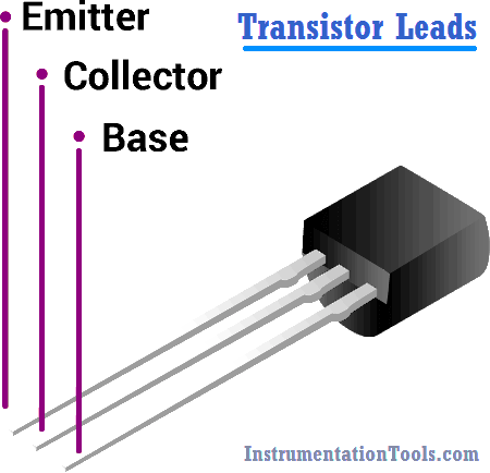
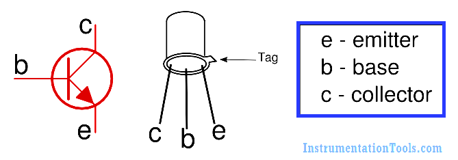
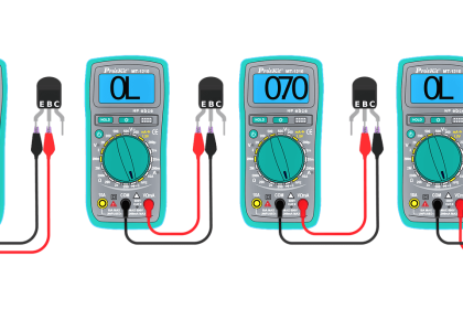
There are three leads in a transistor viz. collector, emitter and base. When a transistor is to be connected in a circuit, it is necessary to know which terminal is which. The identification of the leads of transistor varies with manufacturer. However, there are three systems in general use as shown in Fig.

(i) When the leads of a transistor are in the same plane and unevenly spaced [See Fig.  (i)], they are identified by the positions and spacings of leads. The central lead is the base lead. The collector lead is identified by the larger spacing existing between it and the base lead. The remaining lead is the emitter.

How to Identify the Transistor Leads

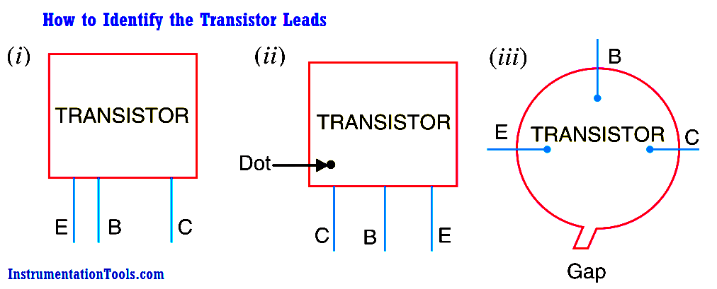
(ii) When the leads of a transistor are in the same plane but evenly spaced [See Fig. (ii)], the central lead is the base, the lead identified by dot is the collector and the remaining lead is the emitter.

(iii) When the leads of a transistor are spaced around the circumference of a circle [See Fig. (iii)], the three leads are generally in E-B-C order clockwise from a gap.

transistor terminals identify

Don't Miss Our Updates
Be the first to get exclusive content straight to your email.
We promise not to spam you. You can unsubscribe at any time.
Invalid email address
You've successfully subscribed !

Continue Reading

Types of Potentiometers – What is a Potentiometer? – Applications
What is Contactor ?
How to Measure capacitance using Multimeter
How are Silicon Chips Disposed?
Power Supply Circuit Fault Analysis
How to Measure Duty Cycle using Multimeter
Share This Article
Facebook Whatsapp Whatsapp LinkedIn Copy Link
Share
2 Comments
  • Earl says:
    August 17, 2016 at 7:06 am

    This is an excellent tool for study

    Reply
  • Erhannis says:
    May 14, 2020 at 3:23 am

    Your leading image contradicts the body of the article: it appears to fall under (i), but labels an outer lead as base rather than the one in the middle.

    Reply

Leave a Reply Cancel reply

Your email address will not be published. Required fields are marked *

Stay Connected

128.3kFollowersLike
69.1kFollowersFollow
210kSubscribersSubscribe
38kFollowersFollow

Categories

Explore More

Clamp Meters Working Principle
What is Cathode Ray oscilloscope ?
Electrical Static Grounding Techniques
What is PCB Corrosion? Electronic Boards Corrosion Prevention
How to Test a Transistor ?
Definition of Accuracy, Precision, Resolution, Range
NO vs NC Contact
How to Test a Battery using a Multimeter?

Keep Learning

What is a Non-Linear Device

What is a Non-Linear Device? Example – Advantages

Clamp Meter

What is a Clamp Meter?

Factors Affecting Inductance

Factors Affecting Inductance

Types of Noise in Electronics

Types of Noise in Electronics

resistor-color-coding-example

IEC labelling for Resistors Color Code

Measure Frequency using Multimeter

How to measure frequency using Multimeter

Diode-testing-with-multimeter

How to Test a Diode using Multimeter

Top Beginner Soldering Mistakes

Top Beginner Soldering Mistakes and How to Avoid Them?

Learn More

Power Electronics Objective Questions

Single-Phase Full Wave AC-DC Converter Questions

Instrument Panel Exhaust Fan Efficiency Improved

Instrument Panel Cooling Efficiency Enhancement

Pressure Sensor Temperature Effects

Temperature Compensation for Pressure Measurement

Frequency Response MCQ

Experimentation of Transfer Function

Thermal Dispersion Flow Switch Working Principle

Thermal Dispersion Flow Switch Working Principle

PLC Ladder Logic Example

PLC Ladder Logic Example

Things You Need to Know About DeviceNet

Things You Need to Know About DeviceNet

DC Generator

DC Generator

Menu

  • About
  • Privacy Policy
  • Copyright

Quick Links

  • Learn PLC
  • Helping Hand
  • Part Time Job

YouTube Subscribe

Follow US
All rights reserved. Reproduction in whole or in part without written permission is prohibited.
Welcome Back!

Sign in to your account

Username or Email Address
Password

Lost your password?