Inst ToolsInst ToolsInst Tools
  • Ask
  • Courses
  • Videos
  • Q & A
    • Interview
      • Instrumentation
      • Electronics
      • Electrical
      • Practical Questions
    • MCQ
      • Instrumentation MCQ
      • Electrical MCQ
      • Electronics MCQ
      • Control Systems MCQ
      • Analog Electronics MCQ
      • Digital Electronics MCQ
      • Power Electronics MCQ
      • Microprocessor MCQ
      • Multiple Choice Questions
  • EE
    • Electronics
      • Electronics Q & A
      • Electronic Basics
      • Electronic Devices & Circuits
      • Electronics Animation
      • Digital Electronics
    • Electrical
      • Electrical Basics
      • Electrical Q & A
      • Power Electronics
      • Electrical Machines
      • Electrical Animation
      • Power Systems
      • Switchgear & Protection
      • Transmission & Distribution
  • Measure
    • Control Valves
    • Calibration
    • Temperature
    • Pressure
    • Flow
    • Level
    • Analyzers
    • Switches
    • Vibration
    • Solenoid Valve
  • Control
    • PLC Tutorials
    • Control Systems
    • Safety Instrumented System (SIS)
    • Communication
    • Fire & Gas System
  • More
    • Design
    • Tools
    • Animation
    • Basics
    • Formulas
    • Standards
    • TextBooks
    • Common
    • Software
    • Excel Tools
    • Erection & Commissioning
    • Process Fundamentals
    • Videos
    • Books
Search
All rights reserved. Reproduction in whole or in part without written permission is prohibited.
Reading: Difference between PFD and P&ID with Example
Share
Notification Show More
Font ResizerAa
Inst ToolsInst Tools
Font ResizerAa
  • Courses
  • PLC Tutorials
  • Control Systems
Search
  • Ask
  • Courses
  • Videos
  • Q & A
    • Interview
    • MCQ
  • EE
    • Electronics
    • Electrical
  • Measure
    • Control Valves
    • Calibration
    • Temperature
    • Pressure
    • Flow
    • Level
    • Analyzers
    • Switches
    • Vibration
    • Solenoid Valve
  • Control
    • PLC Tutorials
    • Control Systems
    • Safety Instrumented System (SIS)
    • Communication
    • Fire & Gas System
  • More
    • Design
    • Tools
    • Animation
    • Basics
    • Formulas
    • Standards
    • TextBooks
    • Common
    • Software
    • Excel Tools
    • Erection & Commissioning
    • Process Fundamentals
    • Videos
    • Books
Follow US
All rights reserved. Reproduction in whole or in part without written permission is prohibited.
Inst Tools > Blog > Basics > Difference between PFD and P&ID with Example

Difference between PFD and P&ID with Example

Process drawings are divided into two major categories. Process Flow diagrams (PFD) and Piping and Instrumentation diagrams (P&ID).

Last updated: September 28, 2022 2:36 pm
R Jagan Mohan Rao
Basics
2 Comments
Share
6 Min Read
SHARE

Basically, Process diagrams can be divided into two major categories.

Contents
Process Flow DiagramPiping and Instrumentation Diagrams
  • Process Flow Diagrams (PFDs).
  • Piping and Instrumentation Diagrams (P&IDs).

Both PFD and P&ID are chemical /process engineering drawings and piping diagrams.

Process Flow Diagram

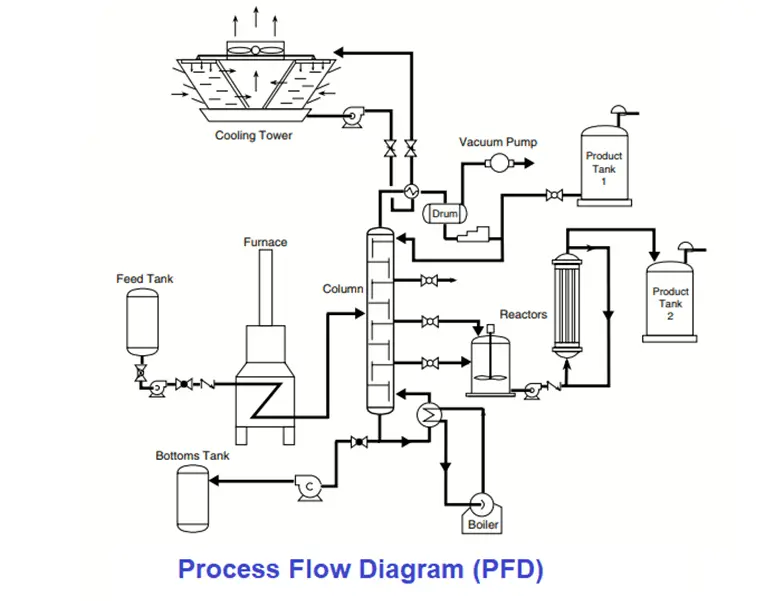
The process flow diagram is also known as “flow sheet” is the first document that enables a clear understanding of the process to be controlled. It shows only the major equipment without details.

That means it shows the crucial elements of the process such as pumps, vessels, turbines, heaters, columns in the system. These, together with the associated material balance, enable a single document to give the control systems engineer a good grasp of the process.

Process Flow Diagram (PFD)

During initial control systems work, the process diagram permits the concepts of process control strategies.

Later, the material balances and operating conditions may be used as input data for the sizing of inline instrumentation such as orifice plates, control valves, and for the selection of their required process instruments such as transmitters, pressure gauges, etc.

The very simplicity of the PFD document allows the control systems engineer to work quickly and logically without being faced with the confusion that is usually associated with more detailed engineering drawings. Despite this simplicity, the process flow diagram carries an enormous amount of information about the process.

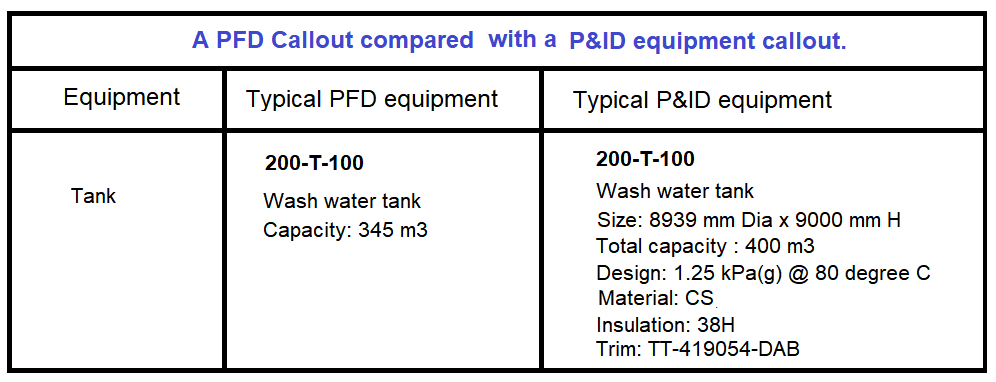
In the figure below, PFD symbols on the left side of the table are shown for the pump, tank, and heat exchanger. For the same pump, tank, heat exchanger many types of P&ID symbols can be chosen while drawing a P&ID based on the application.

PFD symbols versus P&ID Symbols

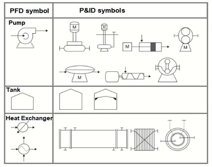
Typical examples found in the process section could include the heat exchangers, distillation columns, or reactors. The process area is a complex collection of equipment that works together with products that will be sent to the final section.

To control a process, one must understand it. A process whose basic characteristics and responses to disturbances are not known thoroughly, cannot be controlled.

The process flow diagram is essential to document the control systems engineer’s understanding of a given process.

To understand a simple flow diagram if it is broken down into sections such as feed, preheating, the process, and the final products as shown in the Process Flow Diagram (PFD) figure.

This simple left-to-right approach allows a technician to identify where the process starts and where it will end finally.

The feed section includes the (process) feed tanks, mixers, piping, and valves. In the second step, the process flow is gradually heated for processing connected with steam or hot oil lines. This section includes heat exchangers and furnaces. In the third section, the process is included.

Piping and Instrumentation Diagrams

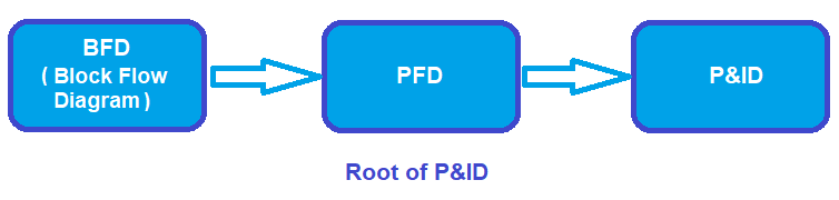
A Piping and Instrument or instrumentation drawing (P&ID) comprises more details than a PFD. It is developed based on information from process flow diagrams, which is developed based on a Block flow Diagram.

Root of P&ID

A P&ID drawing includes both major and minor details of the process plant.

It displays all major equipment like tanks, heat exchangers, pumps, piping details, and also instrumentation details like all pressure temperature and flow instruments, control valves, pressure safety valves, various meters, and tapping details.

Piping and Instrument Drawing

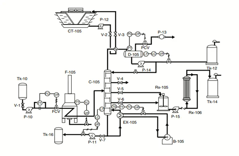
P&ID is a detailed form of PFD. Process engineers, in coordination with piping, instrumentation, electrical, and safety engineers are responsible for preparing the P&IDs.

P&ID drawing has more importance as the basic document for piping engineers for the purpose of material procurement and deciding of pipe routing.

The table below shows how do details of a “Tank” are represented in PFD and P&ID.

Typical PFD and P&ID Equipment

A P&ID (Piping & Instrument Drawing) is a complex reproduction of the various units found in a plant. It is used by people in various departments of the plant.

The primary users of the document after plant startup are process engineers, operators, and instrument and electrical, mechanical, safety, and engineering personnel.

In order to read a P&ID, the technician required an understanding of the equipment, instrumentation, and technology. 

Reference: Piping and Instrumentation diagram Development by Moe Toghrael.

If you liked this article, then please subscribe to our YouTube Channel for Instrumentation, Electrical, PLC, and SCADA video tutorials.

You can also follow us on Facebook and Twitter to receive daily updates.

Read Next:

  • P&ID Guidelines for Pressure Safety Valves
  • Identify Process Variables in P&ID
  • P&ID Guidelines for Storage Tanks
  • Why 4-20 mA Current Signal?
  • Notes on Instrument Ranging
Don't Miss Our Updates
Be the first to get exclusive content straight to your email.
We promise not to spam you. You can unsubscribe at any time.
Invalid email address
You've successfully subscribed !
Performance Characteristics of Sensors and Transducers
Loop Check of 4-20mA or HART Transmitters
Instrumentation Symbols Legend
Basics of Trips, Interlocks, Permissives & Sequences
Transmitters 4-20mA Current Failure Alarm Limits
Share This Article
Facebook Whatsapp Whatsapp LinkedIn Copy Link
Share
2 Comments
  • Anand Thanki says:
    June 19, 2021 at 11:53 pm

    P&ID = Piping and Instrumentation diagram*

    Reply
  • Usman says:
    October 6, 2021 at 9:38 pm

    Of which industry this p id is?

    Reply

Leave a Reply Cancel reply

Your email address will not be published. Required fields are marked *

Stay Connected

128.3kFollowersLike
69.1kFollowersFollow
208kSubscribersSubscribe
38kFollowersFollow

Categories

Recent Comments

  • Guifty Shimica on Top Non-PLC Certification Courses for Automation Professionals
  • Guifty Shimica on Top Non-PLC Certification Courses for Automation Professionals
  • MIHARITSOA Aina Sitraka on Top Non-PLC Certification Courses for Automation Professionals
  • Vaishnavi on Free Instrumentation Course for Trainee Engineers

Related Articles

SMART Transmitter

What is a SMART Transmitter?

Instrumentation Logic Checks

How to Do Logic Checks During Plant Pre-Commissioning

Difference Between Sensor and Transducer

What is the Difference Between Sensor and Transducer?

Instrumentation Project Documents

List of Instrumentation Project Engineering Documents

Why 4-20 mA Current Signal is used instead of Voltage Signal

Why 4-20 mA Current Signal is used instead of Voltage Signal?

Instrument Ranging

Notes on Instrument Ranging

Difference between Analog Signal and Digital Signal

What are Analog and Digital Signals? Differences, Examples

Diaphragm valves

Basics of Valves

More Articles

Root Cause Analysis of Differential Pressure Level Transmitter

Root Cause Analysis of Differential Pressure Level Transmitter

Top Electrical Engineering Interview Questions for Freshers

Latest Electrical Motors Questions and Answers

Digital Electronics Multiple Choice Questions

Ripple Counter Objective Questions

Temperature Coefficient of Resistance

Temperature Coefficient of Resistance (α)

Sugar Plant - Automatic Control of Massecuite Feed

Sugar Plant – Automatic Control of Massecuite Feed

RTD Questions & Answers

RTD Questions and Answers

Control Systems Questions & Answers

Control Systems Objective Questions & Answers – Set 6

Function of Racks in PLC System

Function of Racks in PLC – Types of SIEMENS S7-400 PLC Racks

Follow US
All rights reserved. Reproduction in whole or in part without written permission is prohibited.
Welcome Back!

Sign in to your account

Username or Email Address
Password

Lost your password?