Inst ToolsInst ToolsInst Tools
  • Courses
  • Videos
  • Q & A
    • Interview
      • Instrumentation
      • Electronics
      • Electrical
      • Practical Questions
    • MCQ
      • Instrumentation MCQ
      • Electrical MCQ
      • Electronics MCQ
      • Control Systems MCQ
      • Analog Electronics MCQ
      • Digital Electronics MCQ
      • Power Electronics MCQ
      • Microprocessor MCQ
      • Multiple Choice Questions
  • EE
    • Electronics
      • Electronics Q & A
      • Electronic Basics
      • Electronic Devices & Circuits
      • Electronics Animation
      • Digital Electronics
    • Electrical
      • Electrical Basics
      • Electrical Q & A
      • Power Electronics
      • Electrical Machines
      • Electrical Animation
      • Power Systems
      • Switchgear & Protection
      • Transmission & Distribution
  • Measure
    • Control Valves
    • Calibration
    • Temperature
    • Pressure
    • Flow
    • Level
    • Analyzers
    • Switches
    • Vibration
    • Solenoid Valve
  • Control
    • PLC Tutorials
    • Control Systems
    • Safety Instrumented System (SIS)
    • Communication
    • Fire & Gas System
  • More
    • Design
    • Tools
    • Animation
    • Basics
    • Formulas
    • Standards
    • TextBooks
    • Common
    • Software
    • Excel Tools
    • Erection & Commissioning
    • Process Fundamentals
    • Videos
    • Books
Search
All rights reserved. Reproduction in whole or in part without written permission is prohibited.
Reading: P&ID Guidelines for Pressure Safety Valves
Share
Notification Show More
Font ResizerAa
Inst ToolsInst Tools
Font ResizerAa
  • Courses
  • PLC Tutorials
  • Control Systems
Search
  • Courses
  • Videos
  • Q & A
    • Interview
    • MCQ
  • EE
    • Electronics
    • Electrical
  • Measure
    • Control Valves
    • Calibration
    • Temperature
    • Pressure
    • Flow
    • Level
    • Analyzers
    • Switches
    • Vibration
    • Solenoid Valve
  • Control
    • PLC Tutorials
    • Control Systems
    • Safety Instrumented System (SIS)
    • Communication
    • Fire & Gas System
  • More
    • Design
    • Tools
    • Animation
    • Basics
    • Formulas
    • Standards
    • TextBooks
    • Common
    • Software
    • Excel Tools
    • Erection & Commissioning
    • Process Fundamentals
    • Videos
    • Books
Follow US
All rights reserved. Reproduction in whole or in part without written permission is prohibited.
Inst Tools > Blog > Erection & Commissioning > P&ID Guidelines for Pressure Safety Valves

P&ID Guidelines for Pressure Safety Valves

Last updated: September 29, 2016 11:39 am
Editorial Staff
Erection & Commissioning
1 Comment
Share
2 Min Read
SHARE

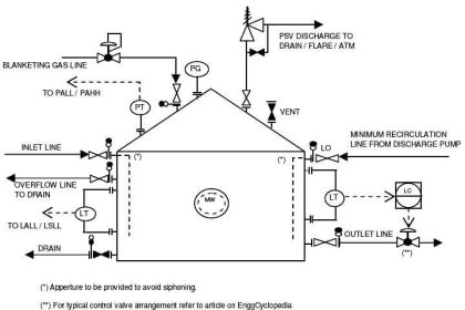
Typical P&ID arrangement – Pressure Safety Valves

P&ID arrangement for Pressure Safety Valves

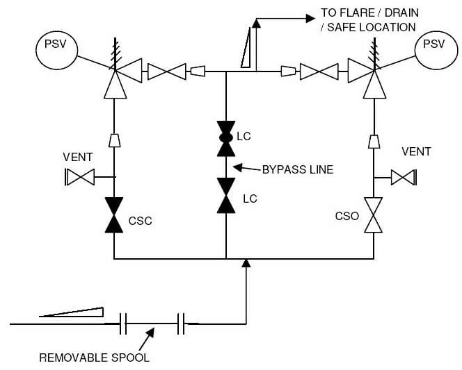
  • The sample drawing presented here represents a typical arrangement generally used to represent safety valves or relief valves on P&ID. First of all a proper safety valve symbol should be selected to represent the control valve as per the project standards.
  • For protecting equipments that are not spared and equipments that cannot be isolated without disrupting the plant / unit a spare safety valve is recommended to be provided as shown in the sample drawing.
  • Generally, the safety valve inlet / outlet nozzles are smaller than the corresponding line sizes. This change in diameter should be clearly indicated in the P&ID with reducer and expander.
  • Block valves should be provided upstream and downstream of the safety valves in case of shutdown and maintenance. Normally provision is made to keep these valves locked or sealed open. The spare safety valve is kept locked or sealed closed, as indicated in the sample drawing.
  • A vent valve is normally provided between the safety valve and upstream block valve.
  • Normally, bypass should provided for safety valves for process or start-up requirements. Type, number and size of bypass valves will depend on the project standards.
  • Depending on the service handled, the discharge from PSV can be either routed to flare system for hydrocarbon service, for closed/open drain systems or to atmosphere at a safe location for non-hazardous service.
  • The inlet lines to the safety valves are always sloped toward to protected equipment and the outlet lines from the safety valves are always sloped towards the flare header / the knock out drum or the safe location.
  • When a PSV is connected to the flare system, the inlet line piping should be equipped with a spool piece to facilitate dismantling, as indicated in the sample drawing. For PSVs discharging to atmosphere, this is not required.
  • All the guidelines given here are very general and may be modified as per specific requirements of any particular project.
Don't Miss Our Updates
Be the first to get exclusive content straight to your email.
We promise not to spam you. You can unsubscribe at any time.
Invalid email address
You've successfully subscribed !

Continue Reading

Pressure Transmitter Vent fittings
How to Install a Rotameter
Cable Trays Glossary
Installation and Calibration of Level Transmitter
What are the Mounting Techniques of Diaphragm Seals?
Pressure Transmitter Manifolds
Share This Article
Facebook Whatsapp Whatsapp LinkedIn Copy Link
Share
1 Comment
  • YK says:
    February 24, 2020 at 9:59 am

    What is the need for vent valve provided between PSV and block valve?

    Reply

Leave a Reply Cancel reply

Your email address will not be published. Required fields are marked *

Stay Connected

128.3kFollowersLike
69.1kFollowersFollow
208kSubscribersSubscribe
38kFollowersFollow

Categories

Explore More

Instrumentation Cables Questions & Answers
Flow Meter Installation Guidelines
Installation Precautions of Thermocouple and RTD
P&ID Guidelines for Storage Tanks
What is Process Flow Diagram (PFD) ?
Tube Fitting Types
Pressure Transmitter Heated Enclosures
Instrument Tube Fitting Installation – Part 3
What is FAT and SAT? Difference between them
Material Certificate versus Positive Material Identification (PMI)

Keep Learning

Good and Bad Wiring Practices

Turbine Flow Meter Installation Procedure

Hook-up Diagram for Pressure Gauge

What is Instrument Hook Up Diagram ?

Impulse Tubing Leak Test Checks

Impulse Tubing Leak Test Checks

Installation & Commissioning Tips for Wireless HART Devices

Installation & Commissioning Tips for HART Devices

DP Level Measurement Problems

DP Level Measurement Problems

P&ID Guidelines for Centrifugal Compressor Systems

P&ID Guidelines for Centrifugal Compressor Systems

Pressure Transmitter Installation

Field Instruments Mounting brackets

Discover More

Tank Level Control Process in PLC

Tank Level Control in PLC

PLC Logic Example on Multiple Switches and Motors

PLC Logic Example on Multiple Switches and Motors

Bubbler Level Measurement Animation

Bubbler Level Measurement Animation

Top 100 Home Automation Projects

Top 100 Home Automation Projects

Siemens PLC-to-PLC Communication Project

GET Command – Siemens PLC-to-PLC Communication Project

As-Interface Protocol Overview

AS-interface and DeviceNet Communication

What is electrical transformer

Transformer Impedance Ratio

repairs of welding cast refractory lined box over the hot spots

Too often done riskily repaired Roof Hot Spots eliminated forever

Follow US
All rights reserved. Reproduction in whole or in part without written permission is prohibited.
Welcome Back!

Sign in to your account

Username or Email Address
Password

Lost your password?