This article elaborates on the basic definition and use of HFT, SFF, and PFDavg terms which are widely used during the SIL verification process.
IEC 61511 defines the safety life cycle where in SIL verification is part of phase 4 (SIS design and engineering).
Before this step Hazard and risk analysis, allocation of safety functions to protection layers, SIS safety requirement specification phases are completed.
SIL (Safety Integrity Level)
A quantitative target for measuring the level of safety in a process.
Defining a target SIL level for the process should be based on the assessment of the likelihood that an incident will occur and the consequences of the incident.
HFT (Hardware Fault Tolerance)
HFT is the ability of equipment to continue to perform the required function in presence of faults or errors.
HFT of device indicates the quality of safety system.
HFT is N means N+1 faults could result into loss of entire safety function.
HFT is 0 means 1 fault can cause loss of entire safety function
(e.g. 1oo1 pressure transmitter used in SIF). Loss of this transmitter will result in the loss of the entire safety loop.
HFT is 1 means 2 faults can cause loss of entire safety function
(e.g. 1oo2 voting)
Following table illustrate the HFT of various voting configuration. So the HFT of XooY = Y-X
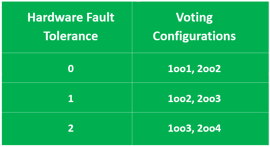
Table 1 : HFT and Voting correlation table
Please be aware that HFT is not synonyms to redundant devices. 2oo2 configuration is also redundant but fault-tolerant.
Higher HFT number will help to achieve higher SIL level of equipment.
SFF (Safe Failure Function)
SFF is basically measure of effectiveness of built-in diagnosis of device.
Any failure that occurs would be of two types:
- Safe failure (λS )and
- Dangerous failure (λD).
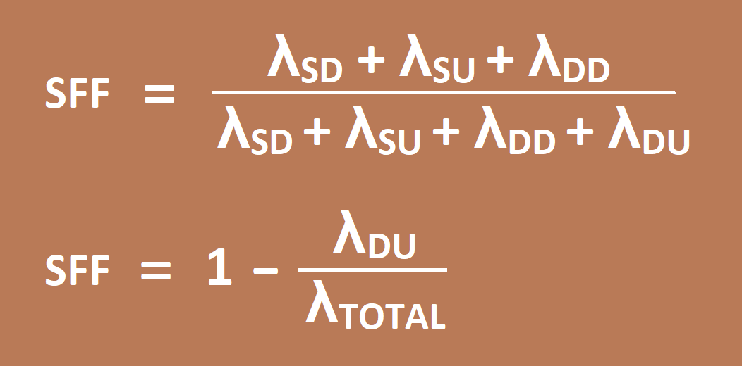
Further, this failure can be detected by means of diagnosis or remain undetected. Be afraid of Dangerous Undetected failure (because it is neither safe nor detected by any means of diagnosis)
Safe failure fraction is the ratio of safe failures(λs =λSD + λSU), plus dangerous detected failures(λDU), divided by the total failure.
Higher the SFF means higher the built-in diagnostic coverage of device, this will help to claim reasonably high SIL level of device.
Architectural Constraints
Architectural constraints are limitations that are imposed on the hardware selected to implement a safety instrumented function, regardless of the performance calculated for a subsystem (e.g PFDavg).
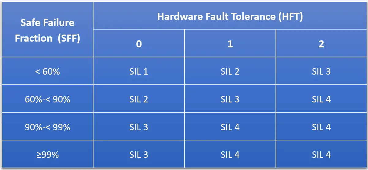
Table 2 : Architectural constraints for type A subsystems – Route 1H
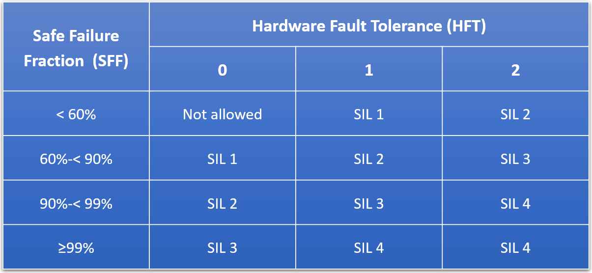
Table 3 : Architectural constraints for type B subsystems – Route 1H
Type A devices
Type A devices are considered to be ‘simple’ devices with known failure modes.
Examples:
- Valve,
- Relay,
- RTD,
- Thermocouple,
- Solenoid,
- limit switches, etc.
Type B devices
Type B devices are considered relatively ‘complex’ devices with unknown failure modes.
Essentially, anything with a microprocessor is considered type B.
Examples:
- Smart transmitters,
- Valve positioners,
- Programmable logic controller (PLC),
- Distributed control system (DCS),
- machine monitoring system (MMS) are considered as type B devices.
Average Probability of Failure on Demand
PFDavg (the average Probability of Failure on Demand) is the probability that a system will fail dangerously, and not be able to perform its safety function when required.
IEC 61508 and IEC 61511 use PFDavg as the system metric upon which the SIL is defined.
Each SIL rating has an associated PFDavg which increases an order of magnitude for each increase in SIL rating.
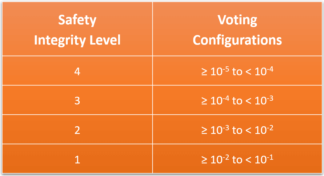
Table 4 : SIL and PFDavg correlation for low demand mode
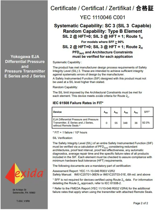
SIL Certificate
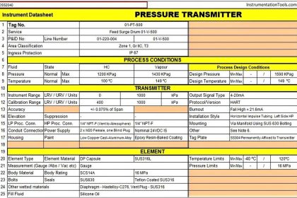
Now let’s take one example of a Pressure transmitter’s SIL certificate and understand the above terms.
Yokogawa make Pressure Transmitter EJA series
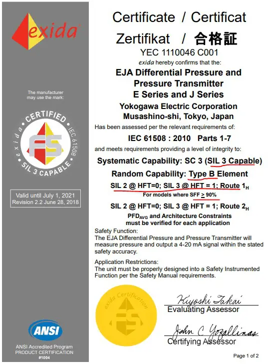
It is type B device
SIL 2 when HFT 0 (1oo1)
SIL 3 when HFT 1 (1oo2)
SFF (from page 2 of certificate) = (0+55+348)/(0+55+348+36)
SFF = 91.79%
Based on Table 3 above when SFF>90% and HFT=0 (1oo1, 2oo2) then you can claim ‘SIL2’ as per the architecture constraint imposed.
Even if 2oo2 (redundant) configuration, you can achieve ‘SIL2’ only.
With this redundancy, it doesn’t simply mean you can achieve a higher SIL level. It has to be understood with HFT levels.
Based on Table 3 above when SFF>90% and HFT=1 (1oo2) then you can claim ‘SIL3’ as per the architecture constraint imposed.
Based on the above certificate of Pressure transmitter, we can summarize PFDavg and final SIL level can be claimed through various voting configuration for the sensor part as following
MTTR = 8 Hrs (Should be part of SRS phase),
Proof test interval = 1 Year (to know the dangerous failure that is not detected by diagnostic)
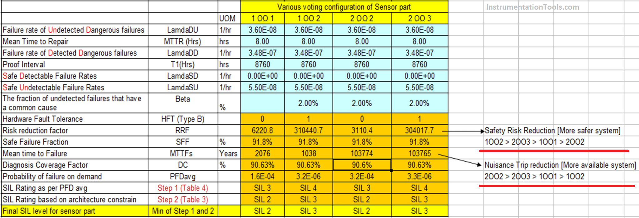
Lower the PFDavg value, Higher the SFF (>90%) value, and higher the HFT level: we can achieve a better SIL level for the SIF device.
A piece of equipment certified for use in SIL 2 applications doesn’t ensure that the entire system/loop will meet SIL 2.
All SIF (Safety instrumented function) components (sensor, logic solver, and final element) must be analyzed according to the latest standard.
Decreasing the Testing interval (increasing testing frequency) and implementing partial stroke testing will improve PFDavg
SIL certificate and safety manuals should be made available for SIF components during the SIL verification process.
Wherever possible conservative failure rate data should be used (industry databases such as OREDA, SINTEF/Exida SERH), sometimes the SIL certificate data is very optimistic.
In this article, I have not described what is Route 2H (prior in use), systematic capability, when fault tolerance needs to be increased (e.g. energize to trip functions), when fault tolerance needs to be decreased (on basis of prior use), low demand mode, high demand mode, etc
Users are advised to get familiar with various definitions, competency requirements, and other guidelines stated in IEC 61508 / IEC 61511 / ISA 84 before starting SIL verification activities.
Author: Jatin Katrodiya
Read Next:
- Instrumentation Earthing
- UPS Selection Factors
- Calculate Transmitter Performance
- Wiring Diagrams of PLC and DCS
- Instrumentation Architecture