Inst ToolsInst ToolsInst Tools
  • Courses
  • Automation
    • PLC
    • Control System
    • Safety System
    • Communication
    • Fire & Gas System
  • Instrumentation
    • Design
    • Pressure
    • Temperature
    • Flow
    • Level
    • Vibration
    • Analyzer
    • Control Valve
    • Switch
    • Calibration
    • Erection & Commissioning
  • Interview
    • Instrumentation
    • Electrical
    • Electronics
    • Practical
  • Q&A
    • Instrumentation
    • Control System
    • Electrical
    • Electronics
    • Analog Electronics
    • Digital Electronics
    • Power Electronics
    • Microprocessor
  • Request
Search
  • Books
  • Software
  • Projects
  • Process
  • Tools
  • Basics
  • Formula
  • Power Plant
  • Root Cause Analysis
  • Electrical Basics
  • Animation
  • Standards
  • 4-20 mA Course
  • Siemens PLC Course
Reading: How to Interchange ON Delay Timer and OFF Delay Timer in a PLC
Share
Font ResizerAa
Inst ToolsInst Tools
Font ResizerAa
  • Courses
  • Design
  • PLC
  • Interview
  • Control System
Search
  • Courses
  • Automation
    • PLC
    • Control System
    • Safety System
    • Communication
    • Fire & Gas System
  • Instrumentation
    • Design
    • Pressure
    • Temperature
    • Flow
    • Level
    • Vibration
    • Analyzer
    • Control Valve
    • Switch
    • Calibration
    • Erection & Commissioning
  • Interview
    • Instrumentation
    • Electrical
    • Electronics
    • Practical
  • Q&A
    • Instrumentation
    • Control System
    • Electrical
    • Electronics
    • Analog Electronics
    • Digital Electronics
    • Power Electronics
    • Microprocessor
  • Request
Follow US
All rights reserved. Reproduction in whole or in part without written permission is prohibited.
Inst Tools > Blog > PLC Tutorials > How to Interchange ON Delay Timer and OFF Delay Timer in a PLC

How to Interchange ON Delay Timer and OFF Delay Timer in a PLC

Last updated: March 4, 2021 3:56 pm
Editorial Staff
PLC Tutorials
2 Comments
Share
4 Min Read
SHARE

Timer functions are most important in PLC Programming. Logics play the important role in PLC Programming.

Contents
ON Delay Timer and OFF Delay TimerPLC Timer FunctionsON DELAY TIMER :OFF DELAY TIMER :List of Inputs and OutputsPLC Program for ON Delay and OFF Delay TimersLadder Logic DescriptionConclusion

According to PLC programmer’s skills, logic will get different in application. In this program, we are going to interchange the function of On Delay Timer and Off Delay timer. AB RSLogix 500 is used to implement the concepts.

ON Delay Timer and OFF Delay Timer

Interchange ON Delay Timer and OFF Delay Timer

PLC Timer Functions

ON DELAY TIMER :

In Layman Statement, Delaying the turning “ON” of the output is On Delay Timer.

Example :

See the image below; if you turn on Input, after 5 sec output will get turn on. It will not turn on immediately.
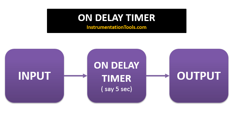
PLC ON DELAY TIMER FUNCTION

In AB PLC, ON Delay Timer is having 6 parameters.

They are

  • Enable Bit (EN): It will turn on when timer is on
  • Done Bit (DN): It will turn on once the timer accumulator value reaches preset value
  • Timer Timing bit (TT) : This bits enable when timer accumulator value is running
  • Preset (PRE): Integer value to set how long timer needs to run or limit starting from zero.
  • Accumulator (ACC): Running value of the timer
  • Time Base : You have options to chose timer base, Sec, cent sec, Mille sec.

OFF DELAY TIMER :

In Layman Statement, Delaying the turning “OFF” of the output is Off Delay Timer.

Example:

See the image below; if you turn on Input, output will turn ON immediately, when you turn OFF the input, It will take 5 sec to turn OFF the output. It will not turn OFF immediately.
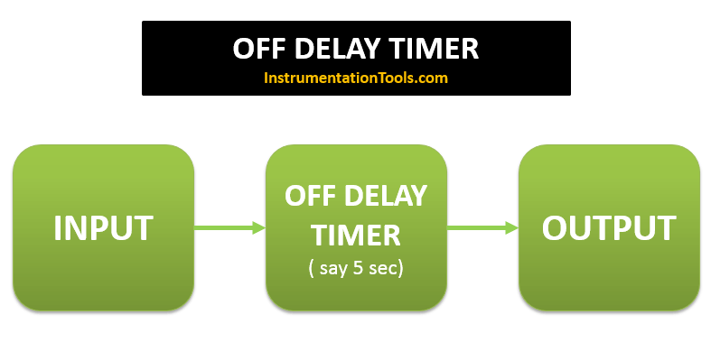
PLC OFF DELAY TIMER FUNCTION

In AB PLC, OFF Delay Timer is having 6 parameters.

They are

  • Enable Bit (EN): It will turn on when timer is on
  • Done Bit (DN): It will turn on once the timer is On and remains ON until timer accumulator value reaches preset value
  • Timer Timing bit (TT) : This bits enable when timer accumulator value is running
  • Preset (PRE): Integer value to set how long timer needs to run or limit starting from zero.
  • Accumulator (ACC): Running value of the timer
  • Time Base: You have options to choose timer base, Sec, cent sec, Millie sec.

List of Inputs and Outputs
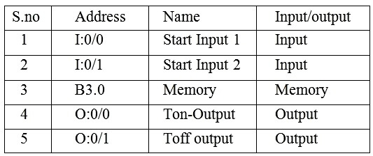
PLC Timer Logic Inputs Outputs

PLC Program for ON Delay and OFF Delay Timers
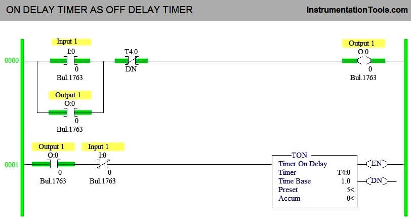
ON DELAY TIMER AS OFF DELAY TIMER
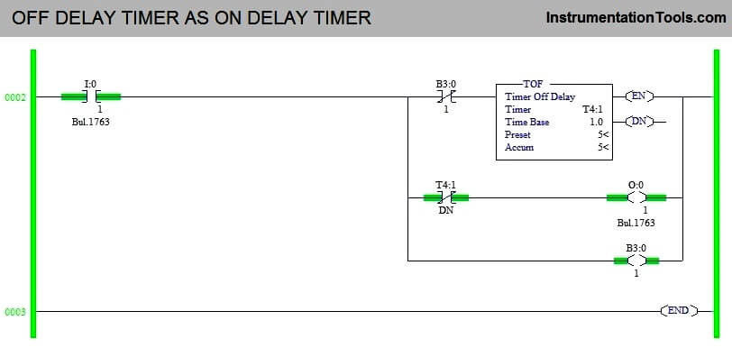
OFF DELAY TIMER AS ON DELAY TIMER

Ladder Logic Description

ON DELAY TIMER AS OFF DELAY TIMER :

1. Rung 0000 :-

Latching is done using output coil to stay ON even Input is turned off. Normally closed timer done bit is used to turn off the output once timer accumulator value reach preset and that make TON to act as TOFF.

2. Rung 0001 :-

since the Start Input is used as normally closed input, Output Coil is attached as interlocking, so that it won’t turn on timer at the beginning of the program.

OFF DELAY TIMER AS ON DELAY TIMER :

3. Rung 0003 :-

Input 2 turned to turn on timer, Memory coil is used to trigger the timer to start count and to make TOFF to act as TON.

Conclusion

The above used timer concept is used to under the function of timer working. It may or may not used in real time application.

Author : Hema Deepan

If you liked this article, then please subscribe to our YouTube Channel for PLC and SCADA video tutorials.

You can also follow us on Facebook and Twitter to receive daily updates.

Read Next:
MCQ on PLC Test

Compare PLC and DCS

What is Relay Logic ?

PLC Maintenance List

Boiler PLC Start-up

Don't Miss Our Updates
Be the first to get exclusive content straight to your email.
We promise not to spam you. You can unsubscribe at any time.
Invalid email address
You've successfully subscribed !

Continue Reading

PLC Sequencer Instruction with Example
Two Hand Control Logic using PLC
PLC Pump Permissive Interlocks
PLC Automatic Pedal Switch for Speed Control
Global Acknowledgment Instruction in Safety PLC
How Modbus is used in Industrial Networks?
Share This Article
Facebook Whatsapp Whatsapp LinkedIn Copy Link
Share
2 Comments
  • SNEHIL SHUKLA says:
    March 31, 2022 at 9:31 pm

    There are two lamp on pressing the start push button the first lamp should go on when the start push button is press again the first lamp should go off and the second lamp should go on if any of the lamp is on for more than 15 second they both the lamp will interchange their status ? Please solve this problem ?

    Reply
  • SNEHIL SHUKLA says:
    March 31, 2022 at 9:32 pm

    How will we be interchange their status?

    Reply

Leave a Reply Cancel reply

Your email address will not be published. Required fields are marked *

Stay Connected

128.3kFollowersLike
69.1kFollowersFollow
210kSubscribersSubscribe
38kFollowersFollow

Categories

Explore More

PLC Program for Water Level Control Logic
Problem on PLC, HMI, VFD, and Motor Circuit
Which Connection is Best for PLC? – Sinking or Sourcing
Developing PLC Logic for Water Pumping and Chemical Addition
PLC Program for Sequential Motor Control
How to Upload Siemens PLC Programs?
PLC Output Types
Parking Garage Indicator: PLC Automation System

Keep Learning

Network Switch

Network Switch Port Allocation Details

Structured Text PID control loop in PLC

How to Program PID Control in PLC with Structured Text?

Search tank in Intouch Scada

Tank Filling and Emptying using Intouch Scada Script

Allen-Bradley PLC

#15 PLC Best Practices – Safe State when PLC Restarts

Sink or source PNP or NPN Normally Open or Normally Closed Input v. output. output

Sink or Source? Normally Open or Normally Closed?

How to Select a SCADA for New Project

How to Select a SCADA for New PLC Project?

How to set password in Siemens HMI

How to Password Protect HMI in Siemens TIA Portal?

Parts of PLC

Parts of PLC

Learn More

Earth Fault

What are Ground Fault and Earth Fault?

Root Locus Concepts Objective Questions

Root Locus in Control Systems

Device Connected to MODEM

Internal Powered Modems

Three Element Drum Level Control System

Three Element Drum Level Control System

What is insulation

What is insulation? How to Choose the Insulation Material?

circuit-breaker-interview-questions-answers

Circuit Breaker Interview Questions & Answers

Instrumentation Basics - Range Conversion Formula and Examples

Instrumentation Basics – Range Conversion Formula and Examples

Electron Spin Resonance Questions & Answers

Electron Spin Resonance

Menu

  • About
  • Privacy Policy
  • Copyright

Quick Links

  • Learn PLC
  • Helping Hand
  • Part Time Job

YouTube Subscribe

Follow US
All rights reserved. Reproduction in whole or in part without written permission is prohibited.
Welcome Back!

Sign in to your account

Username or Email Address
Password

Lost your password?