Inst ToolsInst ToolsInst Tools
  • Courses
  • Automation
    • PLC
    • Control System
    • Safety System
    • Communication
    • Fire & Gas System
  • Instrumentation
    • Design
    • Pressure
    • Temperature
    • Flow
    • Level
    • Vibration
    • Analyzer
    • Control Valve
    • Switch
    • Calibration
    • Erection & Commissioning
  • Interview
    • Instrumentation
    • Electrical
    • Electronics
    • Practical
  • Q&A
    • Instrumentation
    • Control System
    • Electrical
    • Electronics
    • Analog Electronics
    • Digital Electronics
    • Power Electronics
    • Microprocessor
  • Request
Search
  • Books
  • Software
  • Projects
  • Process
  • Tools
  • Basics
  • Formula
  • Power Plant
  • Root Cause Analysis
  • Electrical Basics
  • Animation
  • Standards
  • 4-20 mA Course
  • Siemens PLC Course
Reading: Resonance, Resonant Frequency, Series and Parallel Resonance
Share
Font ResizerAa
Inst ToolsInst Tools
Font ResizerAa
  • Courses
  • Design
  • PLC
  • Interview
  • Control System
Search
  • Courses
  • Automation
    • PLC
    • Control System
    • Safety System
    • Communication
    • Fire & Gas System
  • Instrumentation
    • Design
    • Pressure
    • Temperature
    • Flow
    • Level
    • Vibration
    • Analyzer
    • Control Valve
    • Switch
    • Calibration
    • Erection & Commissioning
  • Interview
    • Instrumentation
    • Electrical
    • Electronics
    • Practical
  • Q&A
    • Instrumentation
    • Control System
    • Electrical
    • Electronics
    • Analog Electronics
    • Digital Electronics
    • Power Electronics
    • Microprocessor
  • Request
Follow US
All rights reserved. Reproduction in whole or in part without written permission is prohibited.
Inst Tools > Blog > Electrical Theory > Resonance, Resonant Frequency, Series and Parallel Resonance

Resonance, Resonant Frequency, Series and Parallel Resonance

Last updated: July 30, 2018 11:32 pm
Editorial Staff
Electrical Theory
No Comments
Share
3 Min Read
SHARE

In the posts on inductance and capacitance, we have learned that both conditions are reactive and can provide opposition to current flow, but for opposite reasons. Therefore, it is important to find the point where inductance and capacitance cancel one another to achieve efficient operation of AC circuits.

Resonant Frequency

Resonance occurs in an AC circuit when inductive reactance and capacitive reactance are equal to one another: XL = XC. When this occurs, the total reactance, X = XL – XC becomes zero and the impendence is totally resistive. Because inductive reactance and capacitive reactance are both dependent on frequency, it is possible to bring a circuit to resonance by adjusting the frequency of the applied voltage. Resonant frequency (fRes) is the frequency at which resonance occurs, or where XL = XC .

The below Equation is the mathematical representation for resonant frequency.
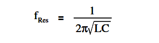
Resonant Frequency

where
fRes = resonant frequency (Hz)
L = inductance (H)
C = capacitance (f)

Series Resonance

Simple R-C-L Circuit

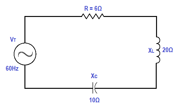
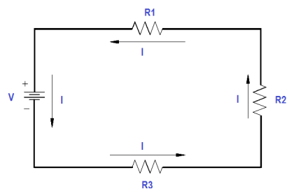
Figure 9 : Simple R-C-L Circuit

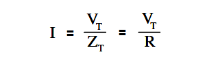
In a series R-C-L circuit, as in Figure 9, at resonance the net reactance of the circuit is zero, and the impedance is equal to the circuit resistance; therefore, the current output of a series resonant circuit is at a maximum value for that circuit and is determined by the value of the resistance. (Z=R)

Series Resonance in series RCL circuit

Parallel Resonance

Resonance in a parallel R-C-L circuit will occur when the reactive current in the inductive branches is equal to the reactive current in the capacitive branches (or when XL = XC ). Because inductive and capacitive reactance currents are equal and opposite in phase, they cancel one another at parallel resonance.

Parallel RLC Circuit

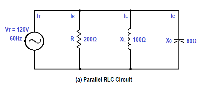
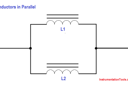
Figure 10 : Simple Parallel R-C-L Circuit

If a capacitor and an inductor, each with negligible resistance, are connected in parallel and the frequency is adjusted such that reactances are exactly equal, current will flow in the inductor and the capacitor, but the total current will be negligible.

The parallel C-L circuit will present an almost infinite impedance. The capacitor will alternately charge and discharge through the inductor. Thus, in a parallel R-C-L, as in Figure 10, the net current flow through the circuit is at minimum because of the high impendence presented by XL and XC in parallel.

Don't Miss Our Updates
Be the first to get exclusive content straight to your email.
We promise not to spam you. You can unsubscribe at any time.
Invalid email address
You've successfully subscribed !

Continue Reading

AC Generation Analysis : Effective Values, Phase Angle and Frequency
Apparent Power, True Power, Reactive Power & Total Power
Series and Parallel Capacitors
Reading Electrical Schematics
Ohm Meter
Three Phase Wattmeter
Share This Article
Facebook Whatsapp Whatsapp LinkedIn Copy Link
Share
Leave a Comment

Leave a Reply Cancel reply

Your email address will not be published. Required fields are marked *

Stay Connected

128.3kFollowersLike
69.1kFollowersFollow
210kSubscribersSubscribe
38kFollowersFollow

Categories

Explore More

DC Generator Theory
Resistivity
Units of Electrical Measurement
Types of AC Generators
Induction Motor Torque Versus Slip
Series-Wound Motor
Wattmeter
Y and Delta Resistor Network Calculations

Keep Learning

Left-hand Rule for Current Carrying Conductors

Magnetism

Inductor Principle

Inductor

Synchronous Motor Principle

Synchronous Motors

Three Phase To Single Phase Wiring Connections

Single Phase Power Wiring Schemes

Voltage and Current Phase Relationships in an Inductive Circuit

Voltage and Current Phase Relationships in an Inductive Circuit

Voltage Polarities

Voltage Polarity and Current Direction

Calculate Power in Series RCL Circuit

Calculate Power in Series RCL Circuit

Simple RL Circuit

Impedance in RL Circuits

Learn More

Difference between Explosion Proof and Intrinsically Safe

Difference between Explosion Proof and Intrinsically Safe

Top Automation Vendors

Top Automation Vendors from Around the World – An Overview

Useful Trigonometry Website for Students Math Help

The Impact of Knowledge Management Platforms on Business Operations

Emerson Smart Wireless gateway

Modbus Function Codes and Addresses

Omron PLC painting program

Product Painting PLC Program using Omron CX-Programmer

Factors to Consider When Choosing Power Tools

Factors to Consider When Choosing Power Tools

Magnetostrictive Tank Gauging Probe

Magnetostrictive Tank Gauging (MTG)

Delete Siemens CPU Memory

How to Delete the Siemens CPU Memory?

Menu

  • About
  • Privacy Policy
  • Copyright

Quick Links

  • Learn PLC
  • Helping Hand
  • Part Time Job

YouTube Subscribe

Follow US
All rights reserved. Reproduction in whole or in part without written permission is prohibited.
Welcome Back!

Sign in to your account

Username or Email Address
Password

Lost your password?