Inst ToolsInst ToolsInst Tools
  • Courses
  • Automation
    • PLC
    • Control System
    • Safety System
    • Communication
    • Fire & Gas System
  • Instrumentation
    • Design
    • Pressure
    • Temperature
    • Flow
    • Level
    • Vibration
    • Analyzer
    • Control Valve
    • Switch
    • Calibration
    • Erection & Commissioning
  • Interview
    • Instrumentation
    • Electrical
    • Electronics
    • Practical
  • Q&A
    • Instrumentation
    • Control System
    • Electrical
    • Electronics
    • Analog Electronics
    • Digital Electronics
    • Power Electronics
    • Microprocessor
  • Request
Search
  • Books
  • Software
  • Projects
  • Process
  • Tools
  • Basics
  • Formula
  • Power Plant
  • Root Cause Analysis
  • Electrical Basics
  • Animation
  • Standards
  • 4-20 mA Course
  • Siemens PLC Course
Reading: Electro-Dynamo Meter Movement
Share
Notification Show More
Font ResizerAa
Inst ToolsInst Tools
Font ResizerAa
  • Courses
  • Design
  • PLC
  • Interview
  • Control System
Search
  • Courses
  • Automation
    • PLC
    • Control System
    • Safety System
    • Communication
    • Fire & Gas System
  • Instrumentation
    • Design
    • Pressure
    • Temperature
    • Flow
    • Level
    • Vibration
    • Analyzer
    • Control Valve
    • Switch
    • Calibration
    • Erection & Commissioning
  • Interview
    • Instrumentation
    • Electrical
    • Electronics
    • Practical
  • Q&A
    • Instrumentation
    • Control System
    • Electrical
    • Electronics
    • Analog Electronics
    • Digital Electronics
    • Power Electronics
    • Microprocessor
  • Request
Follow US
All rights reserved. Reproduction in whole or in part without written permission is prohibited.
Inst Tools > Blog > Electrical Theory > Electro-Dynamo Meter Movement

Electro-Dynamo Meter Movement

Last updated: August 7, 2018 5:06 pm
Editorial Staff
Electrical Theory
No Comments
Share
1 Min Read
SHARE

The electrodynamometer movement (Figure 1) has the same basic operating principle as the D’Arsonval meter movement, except that the permanent magnet is replaced by fixed coils.

The moving coil and pointer, which are attached to the coil, are suspended between and connected in series with the two field coils. The two field coils and moving coil are connected in series such that the same current flows through each coil.

Electrodynamometer Movement Principle

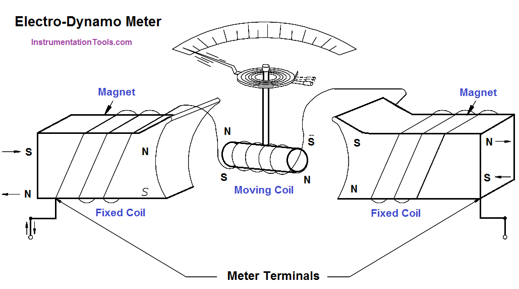
Figure 1 : Electrodynamometer Movement

Current flow through the three coils in either direction causes a magnetic field to be produced between the field coils. The same current flow through the moving coil causes it to act as a magnet exerting a force against the spring. If the current is reversed, the field polarity and the polarity of the moving coil reverse, and the force continues in the same direction.

Due to this characteristic of the electrodynamometer movement, it can be used in both AC and DC systems to measure current. Some voltmeters and ammeters use the electrodynamometer. However, its most important use is in the wattmeter.

Don't Miss Our Updates
Be the first to get exclusive content straight to your email.
We promise not to spam you. You can unsubscribe at any time.
Invalid email address
You've successfully subscribed !

Continue Reading

Electrical Symbols
Induction Motor Torque Versus Slip
Voltmeters
Battery Terminology
DC Machines Terminology
Wattmeter
Share This Article
Facebook Whatsapp Whatsapp LinkedIn Copy Link
Share
Leave a Comment

Leave a Reply Cancel reply

Your email address will not be published. Required fields are marked *

Stay Connected

128.3kFollowersLike
69.1kFollowersFollow
210kSubscribersSubscribe
38kFollowersFollow

Categories

Explore More

Single Phase Power Wiring Schemes
Transformer Voltage Ratio
DC Generator Internal Losses
Parallel Open Circuit Faults
Calculate Power in Parallel RCL Circuit
Inductor
Multimeter & Megger Principle
Parallel Circuit

Keep Learning

4-Wire, Three-Phase Delta Wiring System

4-Wire, Three-Phase Delta Wiring System

Types of Batteries

Types of Batteries

Wiring Diagram

Wiring Diagram

Generator Action in a Motor

Generator Action in a Motor

Capacitor Principle

Capacitor

Three Phase Wattmeter principle

Ampere Hour Meter

Half-Wave Rectifier Circuit

Half-Wave Rectifier Circuit

Inductive Time Constant

Inductive Time Constant

Learn More

Ziegler-Nichols open-loop Tuning

Ziegler-Nichols Open-Loop Method

How to Remove Control Valve Stem Packing Procedure

The Replacement Procedure for Control Valve Stem Packing

Set the S5 timer value by a memory word

Set the S5 Timer Value by a Memory Word

Stability in Frequency Domain

Realization of Basic Compensators

Comparison of Pressure Instruments - Industrial Instrumentation

Comparison of Pressure Instruments – Industrial Instrumentation

Bubble Tube Level measurement

Bubble Tube Level Measurement Principle

Personal Protection Equipment

What is PPE? – Types – Personal Protection Equipment

Identify Instruments in Piping and instrumentation Diagram

Identify Instruments in Piping and instrumentation Diagram

Menu

  • About
  • Privacy Policy
  • Copyright

Quick Links

  • Learn PLC
  • Helping Hand
  • Part Time Job

YouTube Subscribe

Follow US
All rights reserved. Reproduction in whole or in part without written permission is prohibited.
Welcome Back!

Sign in to your account

Username or Email Address
Password

Lost your password?