Transmitters are available with a wide variety of signal outputs. The 4-20mA analogue signal is by far the most commonly used in industrial applications.
Several physical 4-20mA wiring options exist. This guidance note aims to outline these options.
Industrial transmitters are available for monitoring many parameters these including pressure, temperature and flow etc.
Gas detectors / transmitters offer 4-20mA outputs, where 4 mA equates to a zero reading and 20 mA equates a full scale reading of the calibrated range.
This signal is sent to a remotely located control panel. The control panel uses this signal and activates executive actions via relay contacts.
e.g. audible and visual alarms or initiate some trips or even plant shut down procedures.
Transmitters typically require a 24Vdc supply. This supply can be derived local to the transmitter or supplied direct from the associated control panel.
4-20 mA Transmitter Wiring
Several transmitter wiring options exist. The design of the associated control panel dictates which option should be used.
These wiring options include:
- Current source transmitter, non isolated (3 wire)
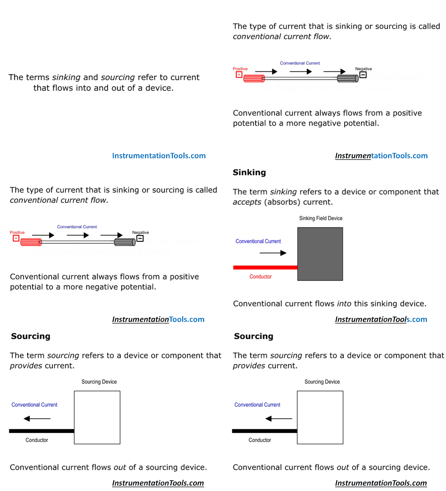
- Current sink transmitter, non isolated (3 wire)
- Fully isolated (4 wire)
- Two wire loop powered transmitters
Most modern transmitters can be wired in a current sink or source format, selection is often made by the use of specific terminals or the location of a link within the transmitter.
However some transmitters may be limited to either a sink or source configuration. Check the transmitters technical manual for the available options.
When transmitters are wired in a current source configuration it follows that the control system will be current sink, and vice versa.
Therefore it is important to qualify whether it is the transmitter or the control system that is to be wired in a specific configuration.
For the purposes for this guidance note it is assumed that both the transmitter and the remote control panel require a 24Vdc supply.
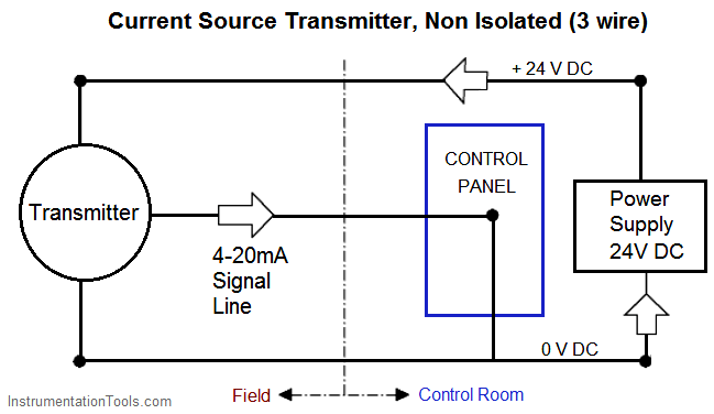
Current Source Transmitter, Non-isolated (3 wire)
This is the most common configuration of modern 4-20mA transmitters.
The transmitter and control panel can use the same 24V and 0V dc supply lines.
The 4-20mA signal flows through the 24V dc line and the signal line to the controller.
Advantages of 3-wire Current Source Transmitter
- Only three cable cores are required to the transmitter.
- A common power supply can be used for both the transmitter and the control panel.
Disadvantages of 3-wire Current Source Transmitter
- Any electrical interference or pick up may be transmitted along the signal line, which could generate a spurious alarm in the control panel
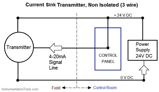
Current Sink Transmitter, Non-isolated (3 wire)
The transmitter and control panel can use the same 0V and 24V dc supply lines.
The 4-20mA signal flows through the 0V dc line and the signal line to the controller.
 Advantages of 3-wire Current Sink Transmitter
- Only three cable cores are required to the transmitter.
- A common power supply can be used for both the transmitter and the control panel.
Disadvantages of 3-wire Current Sink Transmitter
- Any electrical interference or pick up may be transmitted along the signal line, which may generate a spurious alarm in the control panel.
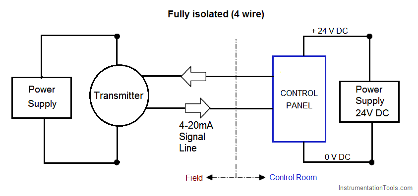
4 wire Fully Isolated
The transmitter and control panel use separate power supplies. The 4-20mA signal flows through two separate cable cores between the transmitter and control panel.
It is assumed that the power to drive the 4-20mA loop is derived from the control panel.
Advantages of 4-wire Transmitter
- Electrical interference on the voltage supply lines will not be transferred to the 4-20mA signal line, reducing the risk of spurious signals being received at the controller.
Disadvantages of 4-wire Transmitter
- An additional cable core is required for each transmitter compared to current sink and source options.
- A separate power supply is required for both the transmitter and control panel.
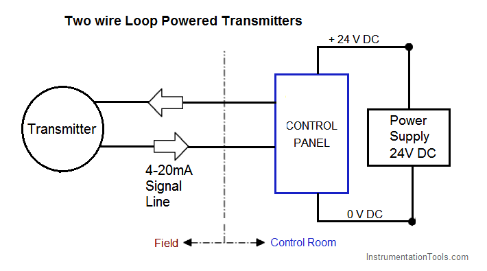
Two Wire Loop Powered Transmitters
This configuration supplies power and 4-20mA signal over a two wire loop connection between the transmitter and the control panel.
Not all transmitters can be wired in this format and must be specifically designed to accommodate this configuration.
Advantages of 2-Wire Loop-Powered Transmitters
- Has low power consumption.
- Only two cable cores are required to the transmitter.
Disadvantages of 2-Wire Loop-Powered Transmitters
- Transmitter discrete fault signalling can not be set at 0mA as this configuration continues to draw some current in a fault condition. This configuration is not suitable for control panels that require a 0mA signal for a fault indication.
Sub 4mA status signalling is limited due the reduced range of mA available between fault and a zero reading.
Not suitable for power hungry transmitters, e.g. catalytic gas detectors, or Infrared gas detectors using optical heating elements.
Basics of 4 to 20 mA
Watch the below video to learn the 4-20 mA basics, history, advantages, and disadvantages.
If you liked this article, then please subscribe to our YouTube Channel for Instrumentation, PLC, and SCADA video tutorials.
You can also follow us on Facebook and Twitter to receive daily updates.
Read Next:
- 4-20mA Transmitter Theory
- End of Line (EOL) Resistor
- What is Fire Alarm System
- Instrumentation Symbols
- What is Process Control?
 Advantages of 3-wire Current Sink Transmitter




thanks for Correct 4- 20 MA Transmitters working principle shown two wire loop Power Transmitters & Fully 4 wire Isolated shown Thanks current sink Transmitters Non isolated 3 wire
good Explantion
One thing I noticed was not mentioned in the wiring of the loops. The limitations and effects of circuit impedance of the loop. I see issues on a regular basis where technicians and engineers have issues with their current loops functioning properly. I have them check the circuit impedance and this is usually the issue, and they have to add a resistor either in parallel or series depending on the requirements.
Good Point. Thanks for sharing.
What should be the value of resistance? And how it should be calculated? Plz explain.
I believe you are asking for the load resistance on the receiving side.
Load resistance should be less than 600 Ohms
Preferably
250 Ohms
Easy conversion to voltage:
4mA -> 1V
20mA -> 5V
Congratulations an excellent contribution to the area of instrumentation
Good Explanation
As per my understanding, the most common used configuration of modern 4-20mA transmitters is Two Wire Loop Powered Transmitters.
Just two cable cores are required to connect from the transmitter to control system. Such loop powered transmitters (with HART) are very popular in the transmitter market and able to cover lots of commonly used process measurement variables such as Pressure, Temperature, Flow, Level and simple Quality (pH, conductivity, moisture, etc).
Question-1
Current source transmitter: “The 4-20mA signal flows through the 24V dc line and the signal line to the controller.”
This sentence is contradicting to me. The 4-20mA signal flow through separate line and not through 24V dc.
Is my understanding is correct?
Question-2
Fully isolated (4 wire): “The transmitter and control panel use separate power supplies.”
Even above sentence is also contradicting to me. The single power supply can be used for this type transmitter & control panel. Only wiring is a change.
Very helpful
how to connect 4 wire to 2 wire loop connection
what is the standard tolerance of cable loop checking
Thank you sir