The End-of-Line Resistor used in fire alarm systems and security systems may look the same as a Terminating Resistor, however the function of the End-of-Line Resistor is completely different.
It’s important to understand that the “signals” used in fire alarm systems are DC, either on or off, not AC, which carries information like video or data.
Because there’s no AC, there are no reflections from the end of the loop; the End-of-Line Resistor is used to pass DC current.
The only purpose is to pass a small supervision current so the fire alarm or security panel can “look” at the wire; if the supervision current stops, the stoppage can be reported immediately, and the trouble will be detected.
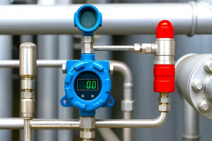
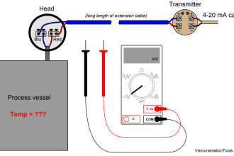
In a Analog Fire & Gas System, Alarm zones or Hooters or Manual Call Points (MCP) or Smoke Detectors are nothing more than current limited dc circuits. If you were to connect a volt meter across an unused zone, depending on the make and model of alarm system, you’d read somewhere close to 12 volts. The alarm system uses this voltage to determine the status of the zone.
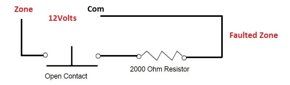
12 volts = There’s an open circuit between zone positive and ground
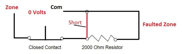
0 volts = There’s a short between zone positive and ground
You’re probable aware that a short in an electrical circuit is a bad thing, in a normal electrical circuit that’s very true. An alarm panel zone differs in that it’s designed to accept a short with no problem.
In fact, if end of line resistors are disabled in programming a short is exactly what the panel is looking for in a normal (not tripped) zone. If the panel see’s zero volts (or close to it) it considers the zone secure. If it see’s 12 volts (or close to it) it considers the zone faulted.
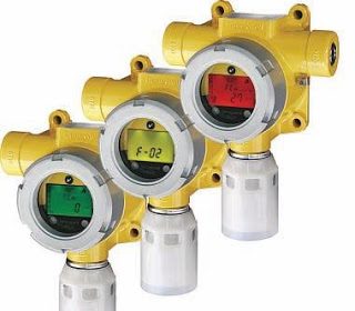
Resistors add an extra degree of security to the zone. Alarm manufacturers design their zones to look for a specific resistance on their circuits. Honeywell for example, uses 2000 ohm resistors on their hardwire zones.
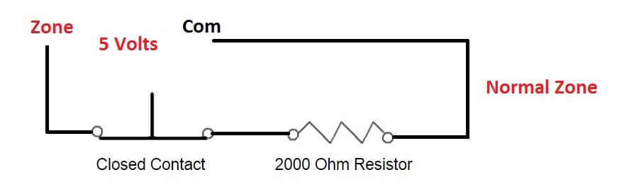
The Honeywell hardwire zone with a 2000 ohm (2k) resistor inline with it will read about 5 volts at it’s terminals,
so now we have:
12 volts = There’s an open circuit between zone positive and ground (the zone is faulted)
5 volts = The circuit is closed with it’s resistor intact (the zone is clear)
0 volts = There’s a short between zone positive and ground (the zone is faulted)
By installing the resistor at the farthest device on the zone (the “end of line”) you create a supervised circuit that can no longer be disabled by simply shorting it’s wire somewhere along the wire run between the control panel and detection device.
Note : EOL Resistor Value will vary from Model to Model & Make to Make.
Note : End of Line (EOL) Resistor Value will vary from vendor to vendor.
Advantages of End of Line Resistor :
To allow the panel’s internal ohmmeter to check the continuity of the wires (supervise the wires), the end-of-line resistor is at the end of the loop: the last device.
Fire
Before getting into the importance of the end-of-line resistor, though, we have to understand the importance of having a fire alarm system in the first place.
Fires are scary. Fires in buildings kill people. Fires are bad.
A properly installed fire alarm system allows people to escape the fire, but there’s a problem. If, at the control panel or somewhere else in the building, something is wrong with the fire alarm system, the fire alarm system might not work. It might not detect a fire, or not being able to tell anyone about the fire, it might not turn on the horns and strobes.
Simple Systems
Fire alarm systems are simple systems. They have to be simple. Remember — the more complicated a system, the more there is to go wrong.
Like turning on a light switch, a very simple fire alarm system is where the input wires start conducting. Basically, the switch (pull station, heat detector, waterflow switch, etc.) turns on the fire horn. This is a simple system that works reliably, at least as long as everything is connected properly.
If a screw comes loose from a pull station, will anyone notice before a fire breaks out? The loose screw means that pulling the lever on the manual pull station doesn’t do anything. Once there’s a raging fire, it’s a little bit late to troubleshoot and fix the wiring issue.
Then again, if between the control panel and the fire horn, a wire breaks, until the building is burning and smoke comes under a closed door, who’s to know. At that point in time, it’s also too late to get out.
Continual Testing of the Continuity of the Wires
A fire can break out anytime. The trouble is, using an ohmmeter, no one is going to spend 24 hours a day 365 days a year making sure the wires are always connected to all the input and output devices.
The fire alarm panel has to do this.
Testing Continuity
Making sure the wires are always connected and not broken, the fire alarm panel is always checking the continuity of the wires. By sending a small current through the wires, it’s supervising them.
If the current stops, the panel turns on its trouble light and buzzer. This is how the owner of the building can see there’s a problem.
Because the trouble buzzer comes on before a fire occurs, the problem with the wiring can be fixed. Now, when a fire breaks out, the fire alarm system will let people know.
Current Limiting End-of-Line Resistor
We still have a current limiting issue. The pull station fully turns on the electrical current. This is how the fire alarm panel finds out about a fire — full current to the panel means fire.
To prevent false alarms while monitoring the wires (supervise of the wires), we can’t fully turn on the current or we get a false alarm. Somehow, we have to limit the current to a bare minimum, allowing just enough current to show the panel’s ohmmeter that the wires are good.
End-of-Line Resistor
That’s where the end-of-line resistor comes in. The resistor limits the current to a bare minimum so the panel doesn’t think it’s detecting a fire, but at the same time it allows the panel to confirm that current is flowing through all the wires.
To make sure all the wires are supervised for continuity, the end-of-line resistor has to be installed at the end of the line — so the electrical current will go through all the wires.
Of course, to allow the panel’s ohmmeter to check the continuity of the wires for the horns, we can’t just twist the wires together at the end; we have to install a resistor there also: to limit the current so the wires aren’t just shorted together.
Continual Continuity Testing
Because fires are anytime, all the wires in the building are always supervised (checked for continuity). Without causing a false alarm or shorting out the horns and strobes, the end-of-line resistor is there to allow the fire alarm panel to continually test (supervise) the wiring.
What are End of Line Resistors and do I need them on my alarm system?
End of line resistors (EOLR) are resistors of a specified value that are used to terminate protective loops or zones.
The purpose of EOLR’s is to allow the control panel to supervise the field wiring for open or short circuit conditions. How the alarm responds to each depends on the panel as well as system zone programming, but generally speaking, an alarm views an open circuit as a fault or alarm condition, and a short circuit as a trouble or alarm condition (if armed). The purpose of EOLR’s is to allow the panel to differentiate between the two conditions by looking for a known resistance.
EOLR’s should be installed at the last device on the loop, electrically speaking, and not inside the control, unless special conditions are met. The benefits of EOLR’s on protective zones with all concealed wiring is commonly argued by professional installers, as well as EOLR’s installed inside the control unit, negating their effectiveness, as well as disabling the EOLR feature and using NC (normally closed) loops for zone definitions. The use of EOLR’s is recommended and is particularly important when the field wiring is subject to damage or compromise.
A fire EOLR should always be installed at the last device and never inside the control or across the zone defined as fire, as this is an inherent safety issue.
Some equipment supports Double End of Line Resistors (DEOLR) to further differentiate between conditions that may exist on the loop.
End Of Line Resistors — The Basics
What are they, and why are they used?
Early security systems used simple electrical circuits to monitor the status of doors and windows. The circuit was either closed or open, and therefore returned full voltage or no voltage at all to the control panel; that was all the system wanted or needed to know. Although such circuits are still in use today, the digital age gave manufacturers the opportunity to make systems more secure.
A resistor is a small semiconductor which resists the flow of electrical current. The current is permitted to flow, but is reduced by the value of the resistor. If a resistor is connected, in series, with a sensor on an alarm circuit, then the control panel no longer sees full voltage across the circuit, but rather a reduced voltage, when the circuit is closed.
Now there are three possible conditions for the control to measure: full open-circuit voltage (if the circuit is open), reduced voltage (if the circuit is closed and secure), and no voltage if the wiring has been compromised. For if the two sides of the circuit are making contact at some point between the control and the resistor, the current has a shortcut back to the control, thus bypassing the resistor. The control will see this no voltage (or very low voltage) as a fault and will alert the user.
Where should resistors be placed?
The method just described can ONLY work if the resistor is placed at the end of the line. There have been many discussions about placing the resistors at the control panel (“in the can,” as the professionals say).
Although there may be practical reasons for doing this, it must be understood that placing resistors anywhere other than the end of the line does NOTHING to supervise the wiring, which is the stated reason for using resistors. A resistor can only supervise the wiring between the resistor and the control.
Why does the wiring need to be supervised? How can the circuit become shorted?
If a potential burglar were to gain access to the zone wiring, the wires could be deliberately shorted, allowing the burglar access to the building at a later time.
Also, a nail or screw (for hanging a painting, photo, etc.) could conceivably pierce both the outer and inner insulation of the wires and make contact between the two conductors. While both of these are admittedly unlikely, they are not impossible.
If a shorted zone is so unlikely, are resistors really necessary?
This question has no simple answer. If it is being asked by a pro installer, there are liability issues to consider, especially if the manufacturer recommends or requires resistors. If a do-it-yourselfer is asking, then no one else can provide a satisfactory answer.
A person installing a system in his/her own home must consider the potential risk of compromised wiring and then make an informed decision. Finally, there is also the question of whether a particular system will even allow the elimination of resistors. If it does not, then the only decision would be where to place them. If resistors are required, but wire supervision is deemed unnecessary, they could be placed at the control.
Resistors seem like such a sensible idea. Is there any reason NOT to use them, and place them at the end of the line as required?
There are a couple of reasons. First, although it is usually quite easy to place a resistor inside a motion detector or glass break sensor, connecting one to a magnetic contact can be a trying experience, especially with recessed contacts. The resistor must be spliced to the wire in some way, and the splice must be pushed back through the hole before the contact is inserted (preferably in such a way that it can be removed if necessary).
On a surface mounted contact, the resistor and splice will be visible, and (partly depending upon the installer\’s skill) can be aesthetically obnoxious. Second, in the event that the control panel is replaced at some future date, the resistors will not be the correct value if a different manufacturer\’s equipment is used.
There is not even a guarantee that the same manufacturer won\’t change resistor values in the future (although this seldom happens). Removing and replacing all the resistors (especially from recessed contacts) in a system has been shown to cause considerable loss of hair, sleeplessness, and outbursts of foul language.
Is there any way to place the resistor inside the can but still supervise the wiring?
Yes. By using a four conductor cable for a two wire sensor, the two free conductors can be used to extend the circuit from the sensor location to the can, through the resistor, and back to the sensor. The resistor would actually be at the end of the line, and supervision would be accomplished.
Are there any other ways in which resistors are used?
Yes. First, fire zones always use resistors, even if the other zones do not. This is because fire sensors are “Normally Open” devices; they only close the circuit when they trip. Therefore, a fire zone in its normal state would appear the same to the system as one where the wire has been cut: namely, open. To prevent this, a resistor is used to close the circuit (with reduced voltage), so that it can be supervised.
Second, some manufacturers allow the use of double EOLR\’s. In this case, a second resistor is added across the terminals of the sensor, so that is in parallel with the circuit. If you will recall, a single resistor allows the system to sense if the circuit is secure, open, or shorted. The second resistor adds the capability of differentiating between an open sensor and an open, or broken, circuit.
Now, if the sensor opens, the current passes through both the series and parallel resistors. The panel senses the reduced voltage and knows that the sensor is, in fact open. With this configuration, zero voltage can mean only one thing: a broken circuit. This constitutes the maximum supervision of zone wiring.
Third, some manufacturers allow the use of “zone doubling,” where two zones, each with a different resistor value, are connected in parallel to the same two terminals. Since they are in parallel, the system sees the total of both reduced voltages when both zones are closed. If one opens, that voltage is removed, and because of the different resistors, the system knows which one is open and which remains closed.
This effectively doubles the number of zones available on the main board, although it does not change the maximum capacity of the system.
Source : douglaskrantz.com, security.livewatch.com


wiring diagram of spf 5000100 resistor
It’s very helpful information ????