As per IEC 61131-3, there are five PLC programming languages, three are graphical. The other two are textual languages.
The three graphical languages are ladder diagram (LD), Function Block Diagram (FBD), Sequential Function Chart (SFC). Two textual languages are Standard Text (ST) and Instruction List (IL).
Out of all the above, various languages have different strengths for different tasks.
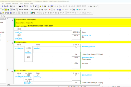
In this article let us discuss Sequential Function Chart (SFC). It is a flow chart-like programming language. The execution of process operations is structured sequentially. It can encapsulate ladder diagram (LD), Function Block Diagram (FBD), Instruction List (IL), and Standard Text (ST) structures to control subroutines.
Sequential Function Chart
Sequential Function Chart (SFC) can be used to structure the internal organization of a program consisting of sub-programs and are also written in other languages of the standard. It can also be used in its pure form of specifying the logical control algorithms.
The SFC programming structure consists of three main elements that organize the control program.
A program in SFC consists of
- Steps (Stages)
- Transitions
- Actions.
Stages
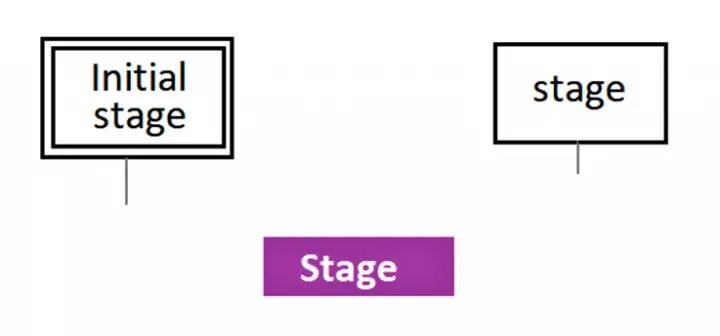
Each stage indicates the state of the process. A step can be active or inactive.
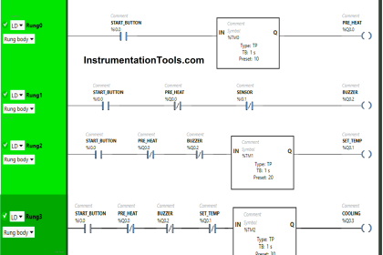
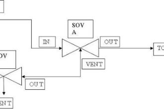
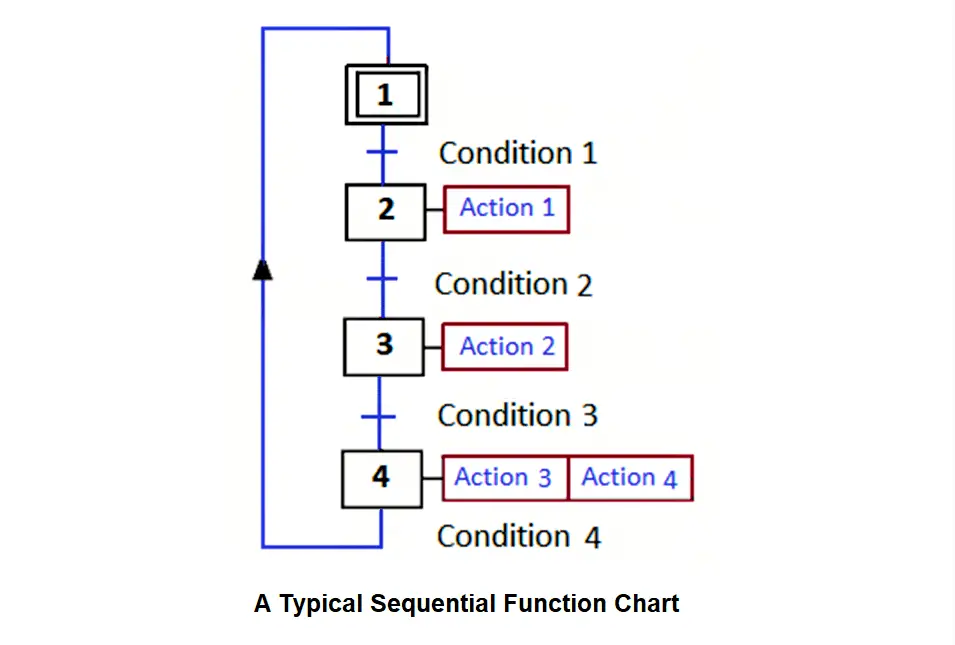
As shown in the figure below, a transition not only can have one input step and one output step but also can have more input steps and more output steps, connected by the directed links.
These sequential flow chart diagrams show the stages in sequential order and are widely used to present algorithms, workflow, or process flow.
Typically, a sequential flow chart displays the steps as charts of various kinds. Their order is established by connecting them with lines.
The stages involve associated actions.
Only some of the stages can be found active in each cycle of the process.
Each stage is identified with a number that must be unique and not it must necessarily keep an order consistent with the sequence of the process.
Transitions
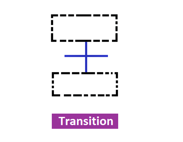
In between two steps, a transition is a step represented by a horizontal line across a vertical line. It is containing the logic condition allowing the transfer from one step to another.
Transitions are associated with a condition, these can be a logical function of variables of input and internal system.
Actions
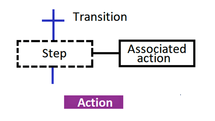
The actions associated with the stages are represented by a rectangle sidebox where the type of action to be carried out is indicated (only the active ones). A stage can have one or more actions associated with it.
The process is broken down into stages, which will be activated sequentially.
One or more actions are associated with each stage. These actions will only be active when the stage is active.
The activation of a transition condition indicates the activation of the next stage and the deactivation of the preceding stage.
Program operation
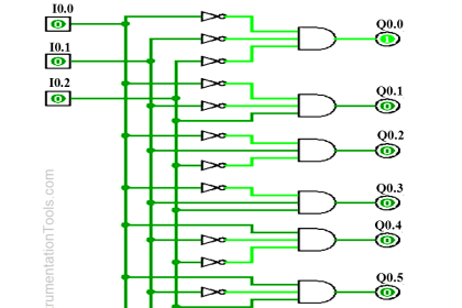
Sequential Flow Chart (SFC) steps are connected with each other same as the flow chart. SFC is conducive to Boolean operation AND or OR decisions. AND decisions are simply placed in series and OR decisions are placed in parallel.
There are two ways to indicate conditions
- Symbolic and
- Literal
Between stage and stage, there must be a transition. The Transition conditions are written to the right of the line that joins them. There may be a jump or step backward seen same as flow charts.
A condition is associated with every transition. If all the input steps of a transition are active, and the transition condition is satisfied then the transition is fired, which means deactivation of all its inputs steps and activation of all its output steps.
Merits of Sequential Function Charts (SFC)
It is a graphical language that provides a diagrammatical representation of control sequences in a program.
- Similar to a flow chart.
- Useful for sequential control operations.
- Shows the main states of a system.
- SFC shows all possible status changes.
Sequence Function Chart (SFC) is suggested by many programming and modeling platforms for logic controllers such as step 7 by SIEMENS and control builder by ABB.
If you liked this article, then please subscribe to our YouTube Channel for PLC and SCADA video tutorials.
You can also follow us on Facebook and Twitter to receive daily updates.
Read Next:
- Process Control
- Power Factor Controller
- Building Management System
- PLC Hardware Troubleshooting
- Instrumentation Symbols Legend