Inst ToolsInst ToolsInst Tools
  • Courses
  • Automation
    • PLC
    • Control System
    • Safety System
    • Communication
    • Fire & Gas System
  • Instrumentation
    • Design
    • Pressure
    • Temperature
    • Flow
    • Level
    • Vibration
    • Analyzer
    • Control Valve
    • Switch
    • Calibration
    • Erection & Commissioning
  • Interview
    • Instrumentation
    • Electrical
    • Electronics
    • Practical
  • Q&A
    • Instrumentation
    • Control System
    • Electrical
    • Electronics
    • Analog Electronics
    • Digital Electronics
    • Power Electronics
    • Microprocessor
  • Request
Search
  • Books
  • Software
  • Projects
  • Process
  • Tools
  • Basics
  • Formula
  • Power Plant
  • Root Cause Analysis
  • Electrical Basics
  • Animation
  • Standards
  • 4-20 mA Course
  • Siemens PLC Course
Reading: Proper Sizing of Conductors
Share
Notification Show More
Font ResizerAa
Inst ToolsInst Tools
Font ResizerAa
  • Courses
  • Design
  • PLC
  • Interview
  • Control System
Search
  • Courses
  • Automation
    • PLC
    • Control System
    • Safety System
    • Communication
    • Fire & Gas System
  • Instrumentation
    • Design
    • Pressure
    • Temperature
    • Flow
    • Level
    • Vibration
    • Analyzer
    • Control Valve
    • Switch
    • Calibration
    • Erection & Commissioning
  • Interview
    • Instrumentation
    • Electrical
    • Electronics
    • Practical
  • Q&A
    • Instrumentation
    • Control System
    • Electrical
    • Electronics
    • Analog Electronics
    • Digital Electronics
    • Power Electronics
    • Microprocessor
  • Request
Follow US
All rights reserved. Reproduction in whole or in part without written permission is prohibited.
Inst Tools > Blog > Electrical Basics > Proper Sizing of Conductors

Proper Sizing of Conductors

Last updated: October 29, 2019 3:10 pm
Editorial Staff
Electrical Basics
No Comments
Share
3 Min Read
SHARE

Proper sizing of conductors is determined by many factors such as industry standards, insurance requirements, local codes, etc.

Proper Sizing of Conductors

The following is based on many years of experience and NFPA 77 “Static Electricity,” 1994. There is no single answer to conductor sizing, although the following guidelines can be provided:

1. Conductors which are connected and disconnected frequently should be light enough to provide an adequate life. A 1/8 inch stainless steel, No. 6 AWG extra flexible copper, 3/16 inch flexible bronze or galvanized steel will carry the current required for static grounding and will fit the majority of applications.

2. Permanently mounted conductors are generally recommended to be at least No. 6 AWG copper, although conductors of #2 to 2/0 are generally used because they are more sturdy. Copper busbar is often used where mounted on a wall or floor. The minimum size recommended is 1/8 inch by 1 inch

3. Outdoor grounding conductors are generally sized for the particular facility and are larger than the minimum required for static grounding requirements alone. A minimum size of #2 AWG is recommended. If fault currents must be considered, a larger size may be necessary.

The question of insulation is important if the static conductor or clamp comes in contact with an object that may be electrically energized.

Another consideration is the operator being in parallel with the static discharge path. If neither of these is a concern, then most users would probably prefer bare conductors that are easier to inspect.

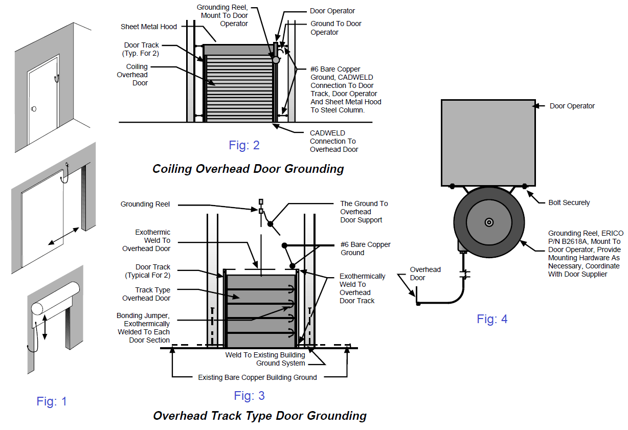
Metal doors must be bonded to the grounding system in critical areas. (Fig. 1, 2, 3, and 4)

Metal doors must be bonded to the grounding system

A personnel static ground bar is necessary to dissipate any static charge before entering a room. (Fig. 5)

Ground bars are available for attachment of static ground clamps. (Fig. 6)

static ground bar

Various bonding jumpers are available from plain or coiled conductors to reels. (Fig. 7)

Electrical bonding jumpers

Fig: 7

Copper ground busbars should be located at room periphery for easy access for ground clamps. (Fig. 8)
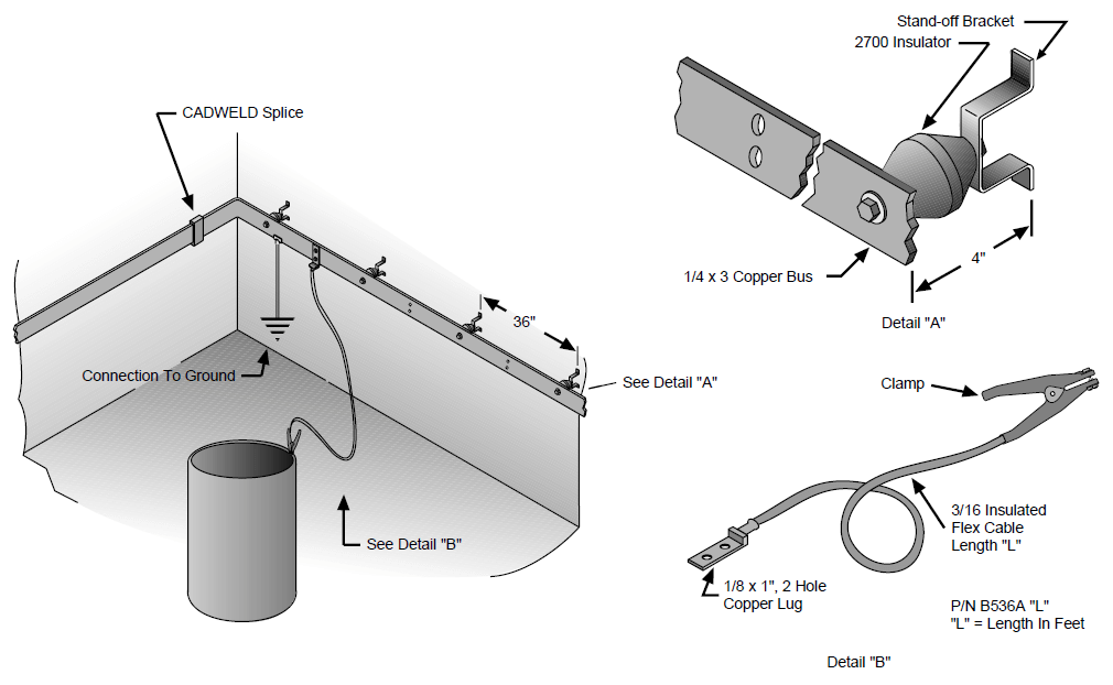
Copper ground busbars

Fig: 8

Reference: erico

Read Next:

  • Importance of Grounding System
  • What is a Ground Detector?
  • Neutral Grounding in Power System
  • Step and Touch Potential in Ground
  • Cable Fault Identification Methods
Don't Miss Our Updates
Be the first to get exclusive content straight to your email.
We promise not to spam you. You can unsubscribe at any time.
Invalid email address
You've successfully subscribed !

Continue Reading

Difference Between Permittivity and Permeability
What is an Electrical Conduit? – Types – How to Choose?
How to Read the Nameplate of a Motor?
Importance of Neutral Wire
What are Ground Fault and Earth Fault?
Difference between Current Transformer and Potential Transformer
Share This Article
Facebook Whatsapp Whatsapp LinkedIn Copy Link
Share
Leave a Comment

Leave a Reply Cancel reply

Your email address will not be published. Required fields are marked *

Stay Connected

128.3kFollowersLike
69.1kFollowersFollow
210kSubscribersSubscribe
38kFollowersFollow

Categories

Explore More

What is insulation? How to Choose the Insulation Material?
What is a Wave Trap? – Power Line Carrier Communication
What is an Auto Changeover Switch?
Various Control Methods in Servo Motor Drives
What is an Overhead Cable? Types of Overhead Conductors
Partial Discharge in Power Lines and its Detection through Sensors
How to Connect a 3 Phase Motor in Star and Delta Connections?
What is a Lightning Arrester? How does it work?

Keep Learning

fundamentals of an AC motor

How does an Electric Motor Operate? – AC Motor Fundamentals

Three-Phase Power Supply

Single Phase versus Three Phase Power

Electrical Engineers Basics

Basic Electrical Engineering Questions & Answers

Difference between Power Cables and Signal Cables

Difference between Power Cables and Signal Cables

What are Switchgear Interlocks?

What are Switchgear Interlocks?

LBB protection relay

What is the LBB Protection Relay? (Local Breaker Backup)

Difference Between Open Circuit and Close Circuit

Difference Between Open Circuit and Close Circuit

Electrical Equipment Selection in Hazardous Area

Hazardous Areas in Industry – Electrical Equipment Selection

Learn More

high-accuracy voltmeter

Electrical Standards

Marking Polarity

DC Circuit Analysis Loop Equations

pH Analyzers Questions and Answers

Combination Electrode Questions & Answers

What is Profibus

What is Profibus? – A Comprehensive Guide for Beginners

Pre-Startup Safety Review (PSSR)

Pre-Startup Safety Review (PSSR)

Pressure Gauge pulsation damping

Pressure Gauge Pulsation Damping

Why is Motor Control Required in Control Systems

Why is Motor Control Required in Control Systems?

PLC Program for Forward and Reverse Motor control

3 Phase Motor Control using PLC Ladder Logic

Menu

  • About
  • Privacy Policy
  • Copyright

Quick Links

  • Learn PLC
  • Helping Hand
  • Part Time Job

YouTube Subscribe

Follow US
All rights reserved. Reproduction in whole or in part without written permission is prohibited.
Welcome Back!

Sign in to your account

Username or Email Address
Password

Lost your password?