Inst ToolsInst ToolsInst Tools
  • Courses
  • Automation
    • PLC
    • Control System
    • Safety System
    • Communication
    • Fire & Gas System
  • Instrumentation
    • Design
    • Pressure
    • Temperature
    • Flow
    • Level
    • Vibration
    • Analyzer
    • Control Valve
    • Switch
    • Calibration
    • Erection & Commissioning
  • Interview
    • Instrumentation
    • Electrical
    • Electronics
    • Practical
  • Q&A
    • Instrumentation
    • Control System
    • Electrical
    • Electronics
    • Analog Electronics
    • Digital Electronics
    • Power Electronics
    • Microprocessor
  • Request
Search
  • Books
  • Software
  • Projects
  • Process
  • Tools
  • Basics
  • Formula
  • Power Plant
  • Root Cause Analysis
  • Electrical Basics
  • Animation
  • Standards
  • 4-20 mA Course
  • Siemens PLC Course
Reading: Phototransistor Working Principle
Share
Notification Show More
Font ResizerAa
Inst ToolsInst Tools
Font ResizerAa
  • Courses
  • Design
  • PLC
  • Interview
  • Control System
Search
  • Courses
  • Automation
    • PLC
    • Control System
    • Safety System
    • Communication
    • Fire & Gas System
  • Instrumentation
    • Design
    • Pressure
    • Temperature
    • Flow
    • Level
    • Vibration
    • Analyzer
    • Control Valve
    • Switch
    • Calibration
    • Erection & Commissioning
  • Interview
    • Instrumentation
    • Electrical
    • Electronics
    • Practical
  • Q&A
    • Instrumentation
    • Control System
    • Electrical
    • Electronics
    • Analog Electronics
    • Digital Electronics
    • Power Electronics
    • Microprocessor
  • Request
Follow US
All rights reserved. Reproduction in whole or in part without written permission is prohibited.
Inst Tools > Blog > Electronic Devices & Circuits > Phototransistor Working Principle

Phototransistor Working Principle

Last updated: July 24, 2017 6:26 am
Editorial Staff
Electronic Devices & Circuits
No Comments
Share
3 Min Read
SHARE

A phototransistor is similar to a regular BJT except that the base current is produced and controlled by light instead of a voltage source. The phototransistor effectively converts light energy to an electrical signal.

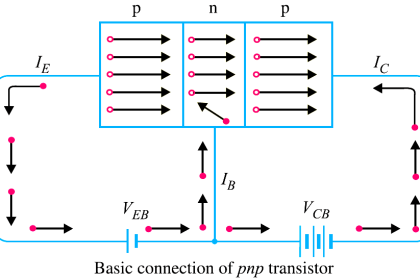
In a phototransistor the base current is produced when light strikes the photosensitive semiconductor base region. The collector-base pn junction is exposed to incident light through a lens opening in the transistor package. When there is no incident light, there is only a small thermally generated collector-to-emitter leakage current, ICEO; this dark cur- rent is typically in the nA range. When light strikes the collector-base pn junction, a base current, Iλ, is produced that is directly proportional to the light intensity. This action produces a collector current that increases with Iλ. Except for the way base current is generated, the phototransistor behaves as a conventional BJT. In many cases, there is no electrical connection to the base.

The relationship between the collector current and the light-generated base current in a phototransistor is

Ic = βDCTλ

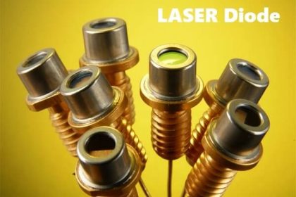
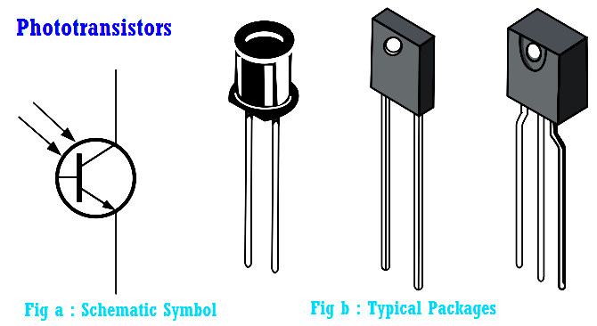
The schematic symbol and some typical phototransistors are shown in Below Figure.

phototransistor symbols

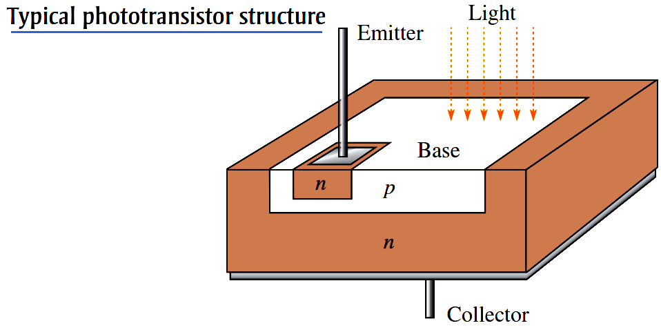
Since the actual photogeneration of base current occurs in the collector-base region, the larger the physical area of this region, the more base current is generated. Thus, a typical phototransistor is designed to offer a large area to the incident light, as the simplified structure diagram in Below Figure illustrates.

phototransistor-structure

A phototransistor can be either a two-lead or a three-lead device. In the three-lead configuration, the base lead is brought out so that the device can be used as a conventional BJT with or without the additional light-sensitivity feature. In the two-lead configuration, the base is not electrically available, and the device can be used only with light as the input. In many applications, the phototransistor is used in the two-lead version.

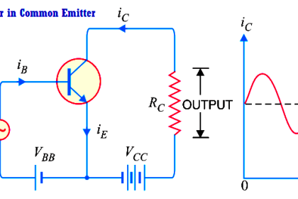
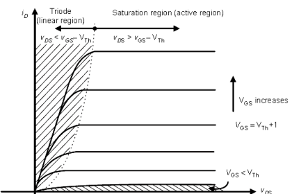
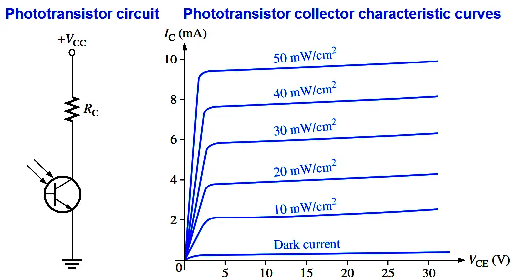
Below Figure shows a phototransistor with a biasing circuit and typical collector characteristic curves. Notice that each individual curve on the graph corresponds to a certain value of light intensity (in this case, the units are mW/cm2) and that the collector current in creases with light intensity.

Phototransistor characteristics

Phototransistors are not sensitive to all light but only to light within a certain range of wavelengths. They are most sensitive to particular wavelengths in the red and infrared part of the spectrum.

Don't Miss Our Updates
Be the first to get exclusive content straight to your email.
We promise not to spam you. You can unsubscribe at any time.
Invalid email address
You've successfully subscribed !

Continue Reading

Transistors Questions & Answers
Electronic Symbols
How a Multi Color LED Works ?
What is a Filter Circuit ?
Classification of Bridge Circuits
Center Tapped Full Wave Rectifier Operation
Share This Article
Facebook Whatsapp Whatsapp LinkedIn Copy Link
Share
Leave a Comment

Leave a Reply Cancel reply

Your email address will not be published. Required fields are marked *

Stay Connected

128.3kFollowersLike
69.1kFollowersFollow
210kSubscribersSubscribe
38kFollowersFollow

Categories

Explore More

Optocouplers Working Principle
Half Wave Voltage Doubler using Diodes
Optoisolator Working Principle
Circuit Elements and Types of Circuits
Basic Transistor Amplifier Circuit Principle
Cathode Ray Tube (CRT)
Diode Clampers Principle
Dependent Current Source

Keep Learning

Applications of Photo diodes

Applications of Photo diodes

Transistor as Switch in Cut off region

Transistor as a Switch Working Principle

pn-junction-with-depletion-layer

How a PN Junction Formed in a Diode

Fluorescent Screen of CRT

CRT Fluorescent Screen

reverse-biased varactor diode

Varactor Diode Operation

Transistor Emitter Feedback Bias

Transistor Emitter Feedback Bias

Methods of Transistor Biasing

Methods of Transistor Biasing

Zener Diode Voltage Regulator Operation

Zener Diode Voltage Regulator Operation

Learn More

Electric Circuits Objective Questions

Electric Circuits Objective Questions – Set 3

Engineering Materials Objective Questions

Engineering Materials Objective Questions

Heat Exchanger Root Cause Analysis

Heat Exchanger Root Cause Analysis (RCA)

HMI screen for operator

Auto Tiffin Box Filling Station

Oil in Water Analyzer Principle

Oil in Water Analyzer Working Principle

Snap Acting Relay Working Principle

Snap Acting Relay Working Principle

Digital Electronics MCQ

Logic Gates and Networks Multiple Choice Questions

MODBUS ASCII Communication Protocol Explained

MODBUS ASCII Communication Protocol Explained

Menu

  • About
  • Privacy Policy
  • Copyright

Quick Links

  • Learn PLC
  • Helping Hand
  • Part Time Job

YouTube Subscribe

Follow US
All rights reserved. Reproduction in whole or in part without written permission is prohibited.
Welcome Back!

Sign in to your account

Username or Email Address
Password

Lost your password?