Inst ToolsInst ToolsInst Tools
  • Courses
  • Automation
    • PLC
    • Control System
    • Safety System
    • Communication
    • Fire & Gas System
  • Instrumentation
    • Design
    • Pressure
    • Temperature
    • Flow
    • Level
    • Vibration
    • Analyzer
    • Control Valve
    • Switch
    • Calibration
    • Erection & Commissioning
  • Interview
    • Instrumentation
    • Electrical
    • Electronics
    • Practical
  • Q&A
    • Instrumentation
    • Control System
    • Electrical
    • Electronics
    • Analog Electronics
    • Digital Electronics
    • Power Electronics
    • Microprocessor
  • Request
Search
  • Books
  • Software
  • Projects
  • Process
  • Tools
  • Basics
  • Formula
  • Power Plant
  • Root Cause Analysis
  • Electrical Basics
  • Animation
  • Standards
  • 4-20 mA Course
  • Siemens PLC Course
Reading: How does Electrical Power Outlet Work?
Share
Notification Show More
Font ResizerAa
Inst ToolsInst Tools
Font ResizerAa
  • Courses
  • Design
  • PLC
  • Interview
  • Control System
Search
  • Courses
  • Automation
    • PLC
    • Control System
    • Safety System
    • Communication
    • Fire & Gas System
  • Instrumentation
    • Design
    • Pressure
    • Temperature
    • Flow
    • Level
    • Vibration
    • Analyzer
    • Control Valve
    • Switch
    • Calibration
    • Erection & Commissioning
  • Interview
    • Instrumentation
    • Electrical
    • Electronics
    • Practical
  • Q&A
    • Instrumentation
    • Control System
    • Electrical
    • Electronics
    • Analog Electronics
    • Digital Electronics
    • Power Electronics
    • Microprocessor
  • Request
Follow US
All rights reserved. Reproduction in whole or in part without written permission is prohibited.
Inst Tools > Blog > Electrical Basics > How does Electrical Power Outlet Work?

How does Electrical Power Outlet Work?

An electrical power outlet is used to distribute electricity to various devices and loads connected to it.

Last updated: February 24, 2023 1:17 pm
Editorial Staff
Electrical Basics
No Comments
Share
5 Min Read
SHARE

Power outlets are an important part of an electrical circuit. It is so easy that you just plug in a laptop on your power outlet socket and your laptop starts charging.

Contents
Power OutletHow does Power Outlets Work?

Basically, a power outlet is thus used to supply electricity to any device connected to it. As electricity is a very important part of our life, it is actually necessary to understand how these outlets work.

In this post, we will learn about the working of power outlets.

Power Outlet

First of all, let us understand what a power outlet is. As you know, AC power has two lines – phase and neutral. From a power distribution grid system, a single-phase system is distributed. This single-phase line (phase and neutral) is then distributed to various circuit breakers in a local panel. From local panels, this electricity is distributed to various sockets which require electricity. These sockets are called power outlets.

Power outlets allow electrical equipment to connect to the electrical supply. You just need to insert the device in the outlet and your device will start working when switched on. Sockets and outlets vary in different countries and they have their own shapes and sizes. But, the working of an outlet is same.

So, simply, a Power outlet is defined as a source for providing power to the final devices for use requiring it. You cannot directly feed power from the substation to your devices. There are various stages in between and due to transformers and various circuit breakers, you get the final safe power supply for your devices.

Power Outlet

How does Power Outlets Work?

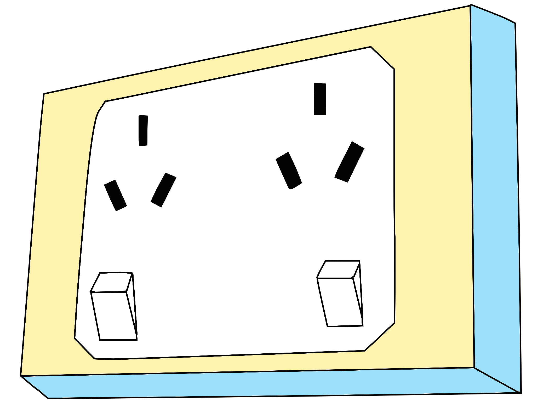
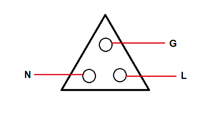
Refer to the below image. As discussed earlier, the AC power has two lines. Out of a transformer or circuit breaker, two wires come in the outlet. One is the phase wire and the other is the neutral wire.

In electrical terms, the proper term used for outlets is hot and neutral. Here, hot means phase wire. The phase wire comes and connects to one end.

The neutral wire is connected to the other end and joins the neutral line in the corresponding circuit breaker or transformer.

Now, due to the switch connected to turn on or off the supply, if the switch is off, then no power will flow from the line to neutral even if the device is connected. If the switch turns on, then the power will flow from the line to the device and then back to the neutral; thus completing the circuit.

This method is actually called polarization. The benefit of polarization is that polarized plugs can only be inserted in one orientation, so the switch to turn any device connected to the socket on or off can be built into the hot lead. In a non-polarized plug, the switch may only open the circuit at the neutral lead, which means that most of the internal circuitry of the device is still considered “hot” and can lead to shock hazards.

Now, let us discuss the third pin – ground. As the name suggests, grounding is provided to protect the device and the personnel from any electrical hazards. A grounding wire is connected separately to each outlet and then is connected to the bottom of the breaker box. This can protect the system from overvoltage or sudden surges.

If there is no ground wire, then when you accidentally touch a device and if there is some voltage malfunction, then you may get a shock or in the second scenario, the device itself will get damaged. Grounding nullifies this by passing the leakage current to the ground.

How do Electrical Power Outlet Work

Basically, the working of outlets are the same, be it whichever country, shape, or size.

In this way, we understand the working of a power outlet.

If you liked this article, then please subscribe to our YouTube Channel for Electrical, Electronics, Instrumentation, PLC, and SCADA video tutorials.

You can also follow us on Facebook and Twitter to receive daily updates.

Read Next:

  • Industrial Circuit Breakers
  • Electrical Motor Concepts
  • Relays in Air Circuit Breaker
  • Induction Motor Over Voltage
  • Purpose of Electrical Substation
Don't Miss Our Updates
Be the first to get exclusive content straight to your email.
We promise not to spam you. You can unsubscribe at any time.
Invalid email address
You've successfully subscribed !

Continue Reading

Lithium-ion Battery Charging Systems
Advantages of Valve Regulated Lead Acid (VRLA) Batteries
Single Phase versus Three Phase Power
VFD Simulator Download – Free Yaskawa V1000 Software
Polarization Index (PI) Test and DA Test
Bus Riser in Switchgear
Share This Article
Facebook Whatsapp Whatsapp LinkedIn Copy Link
Share
Leave a Comment

Leave a Reply Cancel reply

Your email address will not be published. Required fields are marked *

Stay Connected

128.3kFollowersLike
69.1kFollowersFollow
210kSubscribersSubscribe
38kFollowersFollow

Categories

Explore More

Electrical Terminology
What is insulation? How to Choose the Insulation Material?
Automatic Motor Forward and Reverse Control using Timer
What is a Line Choke or Reactor in a VFD?
Why is White Powder Used in Electrical Cables?
Stepper Motor Working Principle
What is a Ground Rod?
Electric Motor Winding Temperature Sensors

Keep Learning

Types of Circuit Breakers

Types of Circuit Breakers, Advantages, Disadvantages

Difference between Signal Cables and Control Cables

Difference between Signal Cables and Control Cables

Difference between PVC, XLPE, and Insulated Cables

Difference between PVC, XLPE, and Insulated Cables

Flame Cables

Difference Between Flame Resistant and Flame Retardant Cables

Electric Stress Control in Cables, Joints and Terminations

Electric Stress Control in Cables, Joints, and Terminations

Understanding Braking Theory in VFD

Understanding Braking Theory in VFD

Humming Sound in Transformer

Why is the Humming Sound Produced in Transformer?

Electrical Power Grid Automation

Electrical Power Grid Automation

Learn More

Interference Immunity (EMC)

Basics of Electromagnetic compatibility (EMC)

Optoisolator Working Principle

Optoisolator Working Principle

LED Indications on PLC

Getting to Know the LED Indications on GE Make PLC

Digital Electronics MCQ

Binary Coded Decimal (BCD) Objective Questions

Voltage Control Methods at Distribution System

Voltage Control Methods at Distribution System

Understanding-a-Process-Control-Loop

Understanding a Process Control Loop

Basics of Butterfly Valves

Automatic Lamp Control in Storage Facility

PLC Program for Automatic Lamp Control in Storage Facility

Menu

  • About
  • Privacy Policy
  • Copyright

Quick Links

  • Learn PLC
  • Helping Hand
  • Part Time Job

YouTube Subscribe

Follow US
All rights reserved. Reproduction in whole or in part without written permission is prohibited.
Welcome Back!

Sign in to your account

Username or Email Address
Password

Lost your password?