Inst ToolsInst ToolsInst Tools
  • Courses
  • Automation
    • PLC
    • Control System
    • Safety System
    • Communication
    • Fire & Gas System
  • Instrumentation
    • Design
    • Pressure
    • Temperature
    • Flow
    • Level
    • Vibration
    • Analyzer
    • Control Valve
    • Switch
    • Calibration
    • Erection & Commissioning
  • Interview
    • Instrumentation
    • Electrical
    • Electronics
    • Practical
  • Q&A
    • Instrumentation
    • Control System
    • Electrical
    • Electronics
    • Analog Electronics
    • Digital Electronics
    • Power Electronics
    • Microprocessor
  • Request
Search
  • Books
  • Software
  • Projects
  • Process
  • Tools
  • Basics
  • Formula
  • Power Plant
  • Root Cause Analysis
  • Electrical Basics
  • Animation
  • Standards
  • 4-20 mA Course
  • Siemens PLC Course
Reading: Motor Inrush Current Measurements
Share
Font ResizerAa
Inst ToolsInst Tools
Font ResizerAa
  • Courses
  • Design
  • PLC
  • Interview
  • Control System
Search
  • Courses
  • Automation
    • PLC
    • Control System
    • Safety System
    • Communication
    • Fire & Gas System
  • Instrumentation
    • Design
    • Pressure
    • Temperature
    • Flow
    • Level
    • Vibration
    • Analyzer
    • Control Valve
    • Switch
    • Calibration
    • Erection & Commissioning
  • Interview
    • Instrumentation
    • Electrical
    • Electronics
    • Practical
  • Q&A
    • Instrumentation
    • Control System
    • Electrical
    • Electronics
    • Analog Electronics
    • Digital Electronics
    • Power Electronics
    • Microprocessor
  • Request
Follow US
All rights reserved. Reproduction in whole or in part without written permission is prohibited.
Inst Tools > Blog > Electrical Basics > Motor Inrush Current Measurements

Motor Inrush Current Measurements

Last updated: November 28, 2016 4:08 am
Editorial Staff
Electrical Basics
1 Comment
Share
4 Min Read
SHARE

Why inrush current important ?

Inrush current, sometimes known as starting current or locked rotor current in motors, can be four to 10 times higher than a motor’s running current. Abnormal levels or duration of inrush current suggests a motor needs maintenance or, potentially, replacement.

Motors Inrush Currents

How and why to measure inrush current

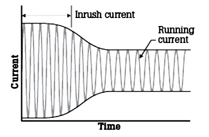
When an electrical device is first powered on, inrush current is the surge or momentary burst of current that flows into it.

Think of a car sitting on flat pavement, parked in neutral, engine off. To get it moving without using the engine, a human would need to give it a substantial push, probably a vigorous leg drive. Once moving, though, the car’s wheels roll more cooperatively with less physical oomph required.

That initial, emphatic leg drive is the equivalent of inrush current. The subsequent, easy-rolling motion equals the steady-state current flow that occurs in a motor once its gears and rotors have been jolted out of inertia and into motion.

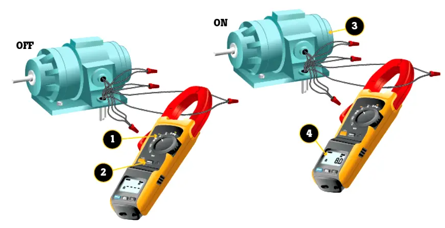
To measure the inrush current, technicians can use either a hard-jawed clamp meter or a flexible current probe. Only meters that offer an inrush button can measure inrush current. Here are steps for measuring it, in this case when using the Fluke 381 (see illustration above):

  1. With the device to be tested turned off, turn the meter’s dial to Clamp Meter Button or a flexible current probe also used.
  2. Center the jaw or flexible probe around the device’s live wire.
  3. Push the inrush button on the face of the meter.
  4. Switch on the device. The inrush current (spike) is displayed in the meter’s display.

Why does this measurement matter?

Newer, high-efficiency motors draw more running current than their predecessors. Knowing the value of inrush current can help a technician locate a startup problem, whether it’s in the motor or in the starting circuit. Inrush measurements are usually recorded in a preventative maintenance log for future reference.

Motor Inrush Current Graph

To provide repeatable motor inrush measurements, advanced clamp meters (such as the Fluke 370 series or the Fluke 381) use a “triggered” mode that synchronizes measurements with the starting current.

Technicians “arm” a meter by pressing its inrush button. The meter is then triggered by the inrush current. Once triggered, this inrush function takes approximately 400 samples over a 100-millisecond period and calculates the actual starting current.

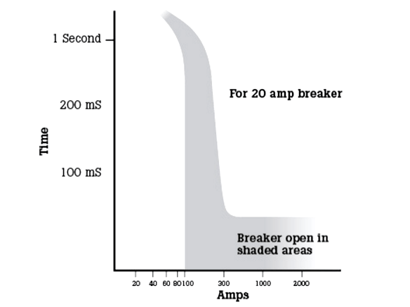
Inrush current may cause a meter’s display to show a value that is higher than the rating of the circuit breaker, yet the breaker does not trip. Why so?

Inrush current can be 4 to 10 times greater than the normal running current, depending on the type of motor. So if a motor’s running current is eight amperes and its circuit breaker is rated for 20 amperes, how is it possible that a clamp meter could display a measurement of 40 amps?

The reason the breaker or overload unit do not trip is because both devices work on a time-vs.-current curve. This curve (see chart) indicates how much current passes through the breaker, and for what length of time, without opening the circuit.

Motor inrush current Problems

Article Source: Fluke

Don't Miss Our Updates
Be the first to get exclusive content straight to your email.
We promise not to spam you. You can unsubscribe at any time.
Invalid email address
You've successfully subscribed !

Continue Reading

What is Variable Air Volume Controller in HVAC?
What is SMPS? – Types of SMPS
What is an Instrument Transformer? – Types, Principle, Advantages
What is ELCB? Principle, Advantages, Disadvantages, Applications
What is Smart or Intelligent MCC?
Difference between Servo Motor and DC Motor
Share This Article
Facebook Whatsapp Whatsapp LinkedIn Copy Link
Share
1 Comment
  • Dulan sanjeewa says:
    December 7, 2016 at 3:18 am

    Help ful document.and also best brand for measurement.fluke.i am also using.

    Reply

Leave a Reply Cancel reply

Your email address will not be published. Required fields are marked *

Stay Connected

128.3kFollowersLike
69.1kFollowersFollow
210kSubscribersSubscribe
38kFollowersFollow

Categories

Explore More

Electrical Drawings
Motor Control Signal Interface
Difference Between Open Circuit and Close Circuit
Electrical Substation – Busbar Arrangements and Layouts
Electric Motors Efficiency Classes
Motor Control Timer Circuit – Automatic Motor START and STOP
What is Vacuum Circuit Breaker?
Difference Between Regenerative and Dynamic Braking

Keep Learning

What is an Oil Separator in HVAC?

What is an Oil Separator in HVAC?

Types of Circuit Breakers

Types of Circuit Breakers, Advantages, Disadvantages

Types of Electrical Loads

Types of Electrical Loads

What is a Bus Coupler in Electrical Panel

What is a Bus Coupler in Electrical Panel?

Difference Between Isolator and Circuit Breaker

Difference Between Isolator and Circuit Breaker

Ground Rod

What is a Ground Rod?

Motor Slip Calculation

Electrical Motor Terms and Concepts

Earthing Calculations

Electrical Earthing Calculations

Learn More

Orifice Taps

Orifice Plate Tapping – Orifice Plate Taps

Single-acting Cylinder OR operation (PLC and Sensors)

Single-acting Cylinder OR Logic Operation (PLC and Sensors)

Pneumatic Level Control Valve

Piping and Instrumentation Drawing (P&ID) Tutorials – Part 3

Single-element drum level control system

Single Element Drum Level Control System

Industrial Automation Cold and Hot Standby

Difference between Cold Standby and Hot Standby

Liquid Level Measurement using Pressure Transmitter

Liquid Level Measurement using Pressure Transmitter Questions

PLC Compressor Control Ladder Logic

PLC Compressor Control Ladder Logic

Power Electronics Objective Questions

Thyristors Objective Questions and Answers

Menu

  • About
  • Privacy Policy
  • Copyright

Quick Links

  • Learn PLC
  • Helping Hand
  • Part Time Job

YouTube Subscribe

Follow US
All rights reserved. Reproduction in whole or in part without written permission is prohibited.
Welcome Back!

Sign in to your account

Username or Email Address
Password

Lost your password?