Inst ToolsInst ToolsInst Tools
  • Courses
  • Automation
    • PLC
    • Control System
    • Safety System
    • Communication
    • Fire & Gas System
  • Instrumentation
    • Design
    • Pressure
    • Temperature
    • Flow
    • Level
    • Vibration
    • Analyzer
    • Control Valve
    • Switch
    • Calibration
    • Erection & Commissioning
  • Interview
    • Instrumentation
    • Electrical
    • Electronics
    • Practical
  • Q&A
    • Instrumentation
    • Control System
    • Electrical
    • Electronics
    • Analog Electronics
    • Digital Electronics
    • Power Electronics
    • Microprocessor
  • Request
Search
  • Books
  • Software
  • Projects
  • Process
  • Tools
  • Basics
  • Formula
  • Power Plant
  • Root Cause Analysis
  • Electrical Basics
  • Animation
  • Standards
  • 4-20 mA Course
  • Siemens PLC Course
Reading: Face to Face Dimension of Control Valve
Share
Notification Show More
Font ResizerAa
Inst ToolsInst Tools
Font ResizerAa
  • Courses
  • Design
  • PLC
  • Interview
  • Control System
Search
  • Courses
  • Automation
    • PLC
    • Control System
    • Safety System
    • Communication
    • Fire & Gas System
  • Instrumentation
    • Design
    • Pressure
    • Temperature
    • Flow
    • Level
    • Vibration
    • Analyzer
    • Control Valve
    • Switch
    • Calibration
    • Erection & Commissioning
  • Interview
    • Instrumentation
    • Electrical
    • Electronics
    • Practical
  • Q&A
    • Instrumentation
    • Control System
    • Electrical
    • Electronics
    • Analog Electronics
    • Digital Electronics
    • Power Electronics
    • Microprocessor
  • Request
Follow US
All rights reserved. Reproduction in whole or in part without written permission is prohibited.
Inst Tools > Blog > Control Valves > Face to Face Dimension of Control Valve

Face to Face Dimension of Control Valve

Last updated: October 3, 2019 4:31 pm
Editorial Staff
Control Valves
No Comments
Share
3 Min Read
SHARE

Typically the face to face dimension requirement of the control valve is specified in the control valve specification. It defines the standards and codes to be used to standardize the face to face dimension of the valves.

The purpose of this standardization is to aid the piping designer in the preliminary design of the overall piping routing in isometric drawing or in the 3D model and also to standardize the control valve dimension to ensure installation interchangeability between a valve that has the same size, same rating, etc.

Please take a note that the dimension provided by the standards and codes is only a preliminary size, the vendor shall confirm that their control valve is in accordance with the standard and codes, otherwise, they shall inform the purchaser about their non-standard size.

Face to Face Dimension

Below are the typical standards and codes that are used to standardize the control valve dimension.

Valve Type Class Size Standards being used
Globe 150 to 600 ½” ~ 16” ANSI/ISA-75.08.01
900 to 2500 ½” ~ 18” ANSI/ISA-75.08.06
Globe All Classes ½” ~ 36” ASME B16.10
High Performance Butterfly Valve 150 to 600 3” ~ 24” ASME B16.10

As preliminary, the following rule of thumb can be used.

The face-to-face dimensions of flanged globe-body control valves of body size ½” to 16” and ASME rating class 150, 300 and 600 should be in accordance with ANSI/ISA-75.08.01. For flanged globe body control valve of body size 16” and larger with ASME rating class 150 to 600, the face to face dimensions of ANSI B16.10 may be used.

The face to face dimensions of flanged globe body control valve of body size ½” to 18” and ASME rating class 900 and above should be in accordance with ANSI/ISA-75.08.06. For globe control valves body size larger than 18”, the face to face dimensions of ASME B16.10 may be used.

Read Also:

  • Control Valve Calibration
  • RTJ & T&G Flange Facing
  • Valve End Connection
  • What are BDV and PSV?
  • Control Valve Characteristic
Don't Miss Our Updates
Be the first to get exclusive content straight to your email.
We promise not to spam you. You can unsubscribe at any time.
Invalid email address
You've successfully subscribed !

Continue Reading

JT Valve Working Principle
ON OFF Valve Preventive Maintenance and Testing Procedure
Control Valve Erosion Problems
Types of Pneumatic Valves : Poppet & Spool
Difference between Quick Opening, Linear & Equal Percentage Control Valve characteristics
How-to do Control Valve Calibration?
Share This Article
Facebook Whatsapp Whatsapp LinkedIn Copy Link
Share
Leave a Comment

Leave a Reply Cancel reply

Your email address will not be published. Required fields are marked *

Stay Connected

128.3kFollowersLike
69.1kFollowersFollow
210kSubscribersSubscribe
38kFollowersFollow

Categories

Explore More

Control Valves Leakage Classifications
Why we Measure Control Valve flow coefficient (Cv)?
Control Valve Recommended Practices for Harsh Process Conditions
What is Butterfly Check Valve ?
Pilot-operated Safety and Relief Valves
Interactive Control Valve Parts Quiz: Drag & Drop Challenge
Control Valve Cavitation and Flashing
Over Pressure cases for Pressure Relief Valve Sizing

Keep Learning

Difference-between-pneumatic-electric-hydraulic-actuators

Difference between Pneumatic, Electrical & Hydraulic Actuators

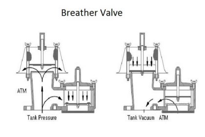
Breather Valve Working Principle

Breather Valve Working Principle

Free Online Control Valves Course

Free Control Valves Course

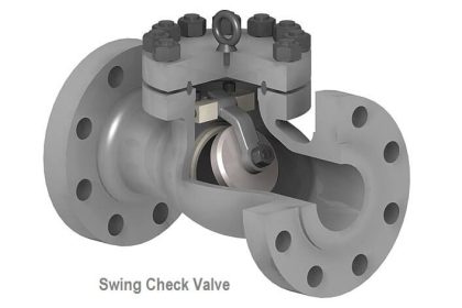
What is Swing Check Valve ?

Pressure Safety Valve Leak Test Procedure

Pressure Safety Valve Leak Test Procedure (PSV Testing)

What is an Altitude Valve

What is an Altitude Valve?

Difference between BDV and PSV

Difference between BDV and PSV

Quick Exhaust Valve (QEV)

Quick Exhaust and Air Operated Valves in Instrumentation Circuit

Learn More

Magnetostrictive Transducers Objective Questions

Magnetostrictive Transducers Objective Questions

What is Multi-touch Technology

What is Multi-touch Technology? – Industrial Automation

What is OTDR Testing

Understanding the Difference between HOP Test and OTDR

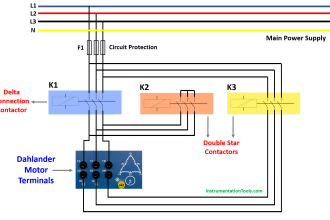
Dahlander Motor Control Circuit

Dahlander Motor Control Circuit and Power Circuit

Flow Transmitters Questions and Answers

Flow Transmitters Questions and Answers – Instruments Test

Electrical Machines Questions and Answers

Induction Motor Rotor Frequency

smart-transmitters-advanced-diagnostics

Smart Transmitters Advanced Diagnostics

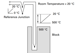
Thermocouples Calibration Errors

Thermocouples Sources of Error

Menu

  • About
  • Privacy Policy
  • Copyright

Quick Links

  • Learn PLC
  • Helping Hand
  • Part Time Job

YouTube Subscribe

Follow US
All rights reserved. Reproduction in whole or in part without written permission is prohibited.
Welcome Back!

Sign in to your account

Username or Email Address
Password

Lost your password?