When a pneumatic actuator requires air pressure applied to two different ports in order to move two different directions (such as the case for cylinders lacking a return spring), the solenoid valve supplying air to that actuator must have four ports: one for air supply (P), one for exhaust (E), and two for the cylinder ports (typically labeled A and B).
4-way Solenoid Valve
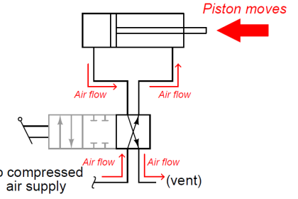
The following diagram shows a 4-way solenoid valve connected to the piston actuator of a larger (process) ball valve:

The same diagram could be drawn using the “triangle” solenoid valve symbols rather than the “block” symbols more common to fluid power diagrams:

Here, the letters “D” and “E” specify which directions air is allowed to flow when the solenoid is de-energized and energized, respectively.
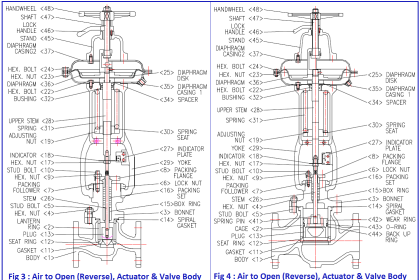
In both of the examples shown above, the solenoid valve forces the piston-actuated valve stem to move down (shut off) when the solenoid is de-energized.
When the solenoid is energized, air is directed to the bottom of the piston (with the top of the piston becoming vented to atmosphere), causing the piston-actuated valve stem to move up (open wide).
An interior view of a standard spool-type 4-way valve of the kind commonly used for directional hydraulic controls is shown here, along with its accompanying schematic symbol:

Note that the actuator (e.g. hand lever, solenoid armature, etc.) has been omitted from this illustration for simplicity. Only the spool and valve body are shown.
In hydraulics, it is common to use the letter “T” to represent the tank or reservoir return connection rather than the letter “E” for exhaust, which is why the supply and vent lines on this valve are labeled “P” and “T”, respectively.
A variation on this theme uses a shorter spool allowing the two control ports to freely pass fluid in the “normal” position:

Such a 4-way valve is useful for applications where the final control element (motor, cylinder) must be free to move rather than be locked in place with the valve in the middle position.
If no center “off” position is needed, the lands may be shortened in such a way that they cannot fully cover the “P,” “1,” and “2” ports simultaneously, making the valve useful only in its two extreme positions:

Not all 4-way valves use the spool-type design. However, the spool valve enjoys the advantage of having pressure balance on its one moving part.
If you examine these cut-away illustrations closely, you will see that the two lands present equal surface areas to the two pressures (pump and tank, “P” and “T”) in perfect vertical symmetry, such that any forces acting on the two lands from fluid pressure do so in opposite directions.
This means there will be no net hydraulic force acting on the spool to interfere with its positioning, thus making it very easy to position by hand lever, solenoid, piston, etc.
A photograph of a Parker brand 4-way pneumatic solenoid valve appears here:

This particular solenoid valve is spring-centered, with one solenoid coil at each end to provide actuation in two different directions. The middle position is one where all ports are blocked, providing a “locked” control position for the pneumatic actuating element fed air by this solenoid valve.
Credits : by Tony R. Kuphaldt – under the terms and conditions of the Creative Commons Attribution 4.0 License


This is very very knowledgeable
I appreciate writer
You are able to honour