Inst ToolsInst ToolsInst Tools
  • Courses
  • Automation
    • PLC
    • Control System
    • Safety System
    • Communication
    • Fire & Gas System
  • Instrumentation
    • Design
    • Pressure
    • Temperature
    • Flow
    • Level
    • Vibration
    • Analyzer
    • Control Valve
    • Switch
    • Calibration
    • Erection & Commissioning
  • Interview
    • Instrumentation
    • Electrical
    • Electronics
    • Practical
  • Q&A
    • Instrumentation
    • Control System
    • Electrical
    • Electronics
    • Analog Electronics
    • Digital Electronics
    • Power Electronics
    • Microprocessor
  • Request
Search
  • Books
  • Software
  • Projects
  • Process
  • Tools
  • Basics
  • Formula
  • Power Plant
  • Root Cause Analysis
  • Electrical Basics
  • Animation
  • Standards
  • 4-20 mA Course
  • Siemens PLC Course
Reading: Locked Open (LO) and Locked Closed (LC) Valves
Share
Font ResizerAa
Inst ToolsInst Tools
Font ResizerAa
  • Courses
  • Design
  • PLC
  • Interview
  • Control System
Search
  • Courses
  • Automation
    • PLC
    • Control System
    • Safety System
    • Communication
    • Fire & Gas System
  • Instrumentation
    • Design
    • Pressure
    • Temperature
    • Flow
    • Level
    • Vibration
    • Analyzer
    • Control Valve
    • Switch
    • Calibration
    • Erection & Commissioning
  • Interview
    • Instrumentation
    • Electrical
    • Electronics
    • Practical
  • Q&A
    • Instrumentation
    • Control System
    • Electrical
    • Electronics
    • Analog Electronics
    • Digital Electronics
    • Power Electronics
    • Microprocessor
  • Request
Follow US
All rights reserved. Reproduction in whole or in part without written permission is prohibited.
Inst Tools > Blog > Control Valves > Locked Open (LO) and Locked Closed (LC) Valves

Locked Open (LO) and Locked Closed (LC) Valves

Locked Open (LO) and Locked Closed (LC) Valves ensure that critical manual valves remain in their intended position during normal operation.

Last updated: October 17, 2023 3:18 pm
R Jagan Mohan Rao
Control Valves
No Comments
Share
5 Min Read
SHARE

In the plant documentation, the abbreviation LC stands for Locked Open and LC for Locked Closed. The valve type may be Ball, Butterfly, Gate, Globe, or any other.

Contents
Mechanical Locking of ValvesWhy Use Locked Open or Locked Closed?Locked Open (LO) ValveLocked Closed (LC) Valve

Locked valves in the industrial environments are those valves their requirement is identified during the design phase, as being essential to the safety and integrity of the facility.

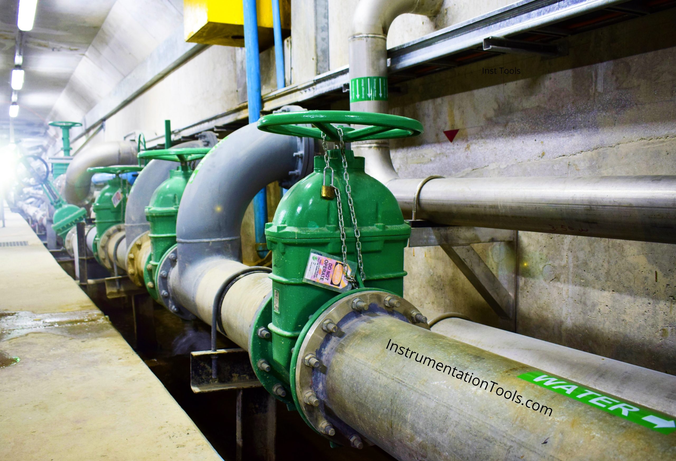
Valves are often specified with an arrangement to add a locking device as part of the scope of supply of a vendor.

The locking device may be either a cleat located on the body of the valve, through which a chain or a D-lock can be placed, or a plate with a drilled hole on a valve.

This kind of locking arrangement is identified on Process Flow Drawing (PFD) or Process and Instrumentation Drawings (P&ID) and the other related documentation as LC (locked closed) or LO (locked open).

The method of Locked open and locked closed prevents the accidental operation of crucial valves in pressure safety relief lines or liquid drain lines.

To change the function of a valve from open to close or from close to open, it will only be done by authorized operators designated by the name “key personnel.”

To this day this is the preferable and favorite protective method of valves to be locked open or locked closed.

Mechanical Locking of Valves

Lock Open (LO) And Lock Close (LC) Valves

The need for a more sophisticated method of locking became more important to prevent the possibility of sabotage also had to be considered.

These concerns led to the development of the mechanical interlocking system, which comprises a hard metal piece of equipment that can be fitted to all manual and actuated valves. Its operation to be carried out in an individual or sequence with other valves.

An example of a sequence locking procedure is a pig launcher/receiver system in Oil and Gas industry.

One key is used to lock open and the other key is used to lock closed the valve.

The keys used to lock closed the valve or lock open the valve are always retained in a key cabinet that is located in the control room.

Only an authorized “key” personnel will have access to this cabinet.

Why Use Locked Open or Locked Closed?

 The use of Locked open or Locked closed (LO/LC) valves is often related to safety.

This kind of arrangement provides a means to ensure that some critical manual valves remain in their intended position during normal operation.

They are not un-intentionally operated. Working with such a system requires strict procedures to manage the position of the valves and to manage their locks.

It will establish a strong safety culture within the organization.

Locked Open (LO) Valve

For example, pressure vessels are mounted with Pressure Safety Valves (PSV) with valves in Locked Open (LO) valves would be on the inlet and the outlet of Pressure Safety Valves (PSV).

The Locked open valves are a kind of isolation valves on the inlet and outlet of a PSV that must remain open during normal operation in order that they can protect the equipment on which they are mounted.

Unintentional or accidental closure of those valves during normal operation could prove catastrophic consequences. Hence it is the requirement to lock them in their open position.

Locked Closed (LC) Valve

For example, a valve in locked Close (LC) would be on a line to the maintenance closed drains system.

Entry of flammable hydrocarbons in the maintenance closed drains system during normal operation is hazardous. That is the reason the isolation valve on the drain line must be closed during normal operation.   

  • The locked status at site shall be maintained in the appropriate register.
  • Some organizations audit on LC, LO status for every four months.
  • Permit to work system procedure need authorization while changing normal state of a locked valve.

Reference: Valve Hand Book by Peter Smith, RW Zappe.

If you liked this article, then please subscribe to our YouTube Channel for Instrumentation, Electrical, PLC, and SCADA video tutorials.

You can also follow us on Facebook and Twitter to receive daily updates.

Read Next:

  • Valve Interlock
  • Cavitation Test Setup
  • Solenoid Valves Terminology
  • Terms Used in Control Valves
  • Control Valve Air Lock Relay
Don't Miss Our Updates
Be the first to get exclusive content straight to your email.
We promise not to spam you. You can unsubscribe at any time.
Invalid email address
You've successfully subscribed !

Continue Reading

Valve Materials Comparison Notes
Difference between Rotary Shaft Valves and Sliding Stem Control Valves
Interactive Control Valve Parts Quiz: Drag & Drop Challenge
Working Principle of Self Operated Valves
Difference between BDV and PSV
Spring and Diaphragm Pneumatic Actuators
Share This Article
Facebook Whatsapp Whatsapp LinkedIn Copy Link
Share
Leave a Comment

Leave a Reply Cancel reply

Your email address will not be published. Required fields are marked *

Stay Connected

128.3kFollowersLike
69.1kFollowersFollow
210kSubscribersSubscribe
38kFollowersFollow

Categories

Explore More

Control Valve Volume Booster Working Principle
Components of Shutdown Valve
Pressure Relief Valve Terminology
Self-Actuated Valves, Pneumatic & Hydraulic Actuators
Electro Pneumatic Valve Positioner Schematic & Principle
Types of Control Valves
Diaphragm Valves Construction, Types, Stem & Bonnet Assembly
Safety Relief Valve Material Selection

Keep Learning

Flapper nozzle system

What is Flapper Nozzle System ?

valve actuator yoke

Advantages and Disadvantages of Valve Actuators

Purpose of Isolation valve

What are Isolation valves? – Purpose, Types, Configurations

needle valve applications

Applications of Needle Valves

Y Body Globe Valve

Globe Valve Body Design

Solenoid Valve Functional Testing

Solenoid Valve Functional Testing

electric motor actuator principle

What is a Electric Motor Actuator ?

Basics of Valves Interview Questions & Answers

Basics of Valves Interview Questions & Answers

Learn More

Seismic Transducers Objective Questions

Seismic Transducers Objective Questions

Types of Digital Outputs in PLC

Types of Digital Outputs in PLC

DP Transmitter Capillary arrangement

DP Transmitter Interface Level Measurement Principle, Limitations, Selection, Installation, Design & Calibration

Force Measurement Objective Questions

Force Measurement Objective Questions

Electrical & Electronics Measurements Objective Questions

Electrical & Electronics Measurements Objective Questions – Set 2

DC Generator

DC Generator

Transistor as Switch Working Animation

How a Transistor Switch Works

Power Electronics Objective Questions

Power Electronics Diode Circuits MCQ

Menu

  • About
  • Privacy Policy
  • Copyright

Quick Links

  • Learn PLC
  • Helping Hand
  • Part Time Job

YouTube Subscribe

Follow US
All rights reserved. Reproduction in whole or in part without written permission is prohibited.
Welcome Back!

Sign in to your account

Username or Email Address
Password

Lost your password?