The control valves flow direction based on different factors like delta pressure, cavitation, failure action, and percentage of control valve opening.
Control Valve Flow Direction

Types of control valve flow direction
- Flow to Open (FTO)
- Flow to Close (FTC)
Flow to Close (FTC)
When the fluid passes on top of the plug, it gives a closing action to the plug. This is called the flow to close (FTC) type flow direction. The effects of cavitation are less and it requires more breakaway torque to open and less torque for closing the valve. This is mainly used for low-pressure applications.
Flow to close FTC) is used in anti-cavitation trim with rotary valves are the special applications.
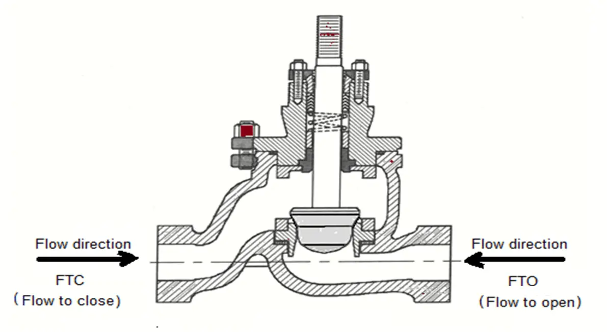
Flow to Open (FTO)
When the fluid flows pass through and faces the plug directly, it gives an opening act to the plug. This is called a flow-to-open (FTO) type of flow direction.
As the flow is upward direction on the plug, it requires higher closing torque and less opening torque and is mainly used for high-pressure applications.
Unless there is a special reason almost all general service applications are Flow to open (FTO).
Flow Direction of Ball Valve
The flow direction of ball valves is bidirectional irrespective of design such as floating ball or trunnion mounted. On the upstream or downstream, two identical round seats are fixed and the ball will move on it.
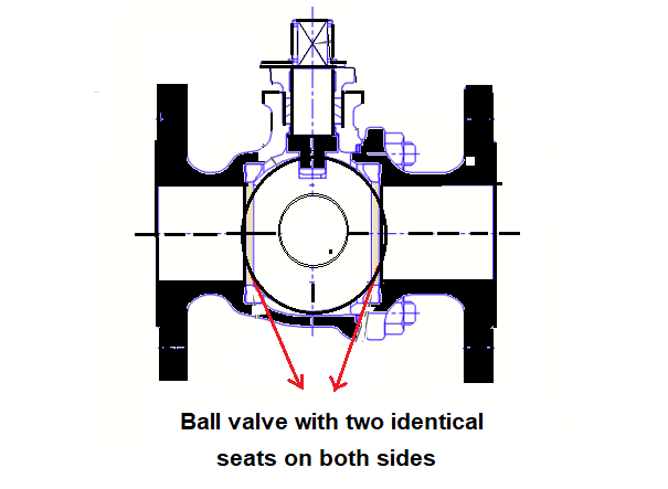
Image Courtesy: Neles
Changing the direction of the ball valve during installation does not affect the sealing performance.
Unidirectional Ball Valve
There are certain ball valves that are marked flow direction need to pay attention to them while installation.
For example, the C type ball valve is mounted on a single seat is meant for the unidirectional flow control valve.
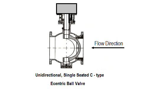
Image Courtesy: Metso
Also called half ball valve or eccentric ball valve.
In certain working conditions, the double-seated ball valves are designed in a single flow direction. In the upstream side of the ball, a hole is drilled for the pressure relief side. This is found in liquid chlorine, LNG applications.
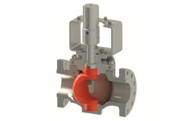
Image Courtesy: Emerson
Single seated ball valves V port ball valves, single-seat shall be connected to the upstream side of the valve.
Flow Direction of Globe Valve
The globe valve is mostly used for throttling flow control. Shut off is accomplished by moving the disc against the flow stream. The flow pattern across globe valve changes in direction, resulting in greater resistance to flow results in high-pressure drop.
The globe valve must be mounted in proper relation to the media flow as indicated by the flow direction marked on the valve body.
This valve is considered unidirectional and must be installed on the pressure side.
For high-temperature steam service applications, globe valves installed so that pressure is above the disc.
For temperature application, the globe valves installed so that pressure is below the disc. This promotes smooth operation, helps protect the packing, and helps the certain amount of erosion action on the seat and disc surfaces.
Flow Direction of Butterfly Valve
Butterfly valves are bidirectional but do not have a preferred flow direction. However, it is strongly suggested to install in the preferred flow direction, as it will extend the valve’s lifespan and will also lower the operating torque.
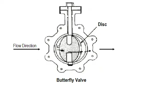
Image Courtesy: Metso
Read Next
- Control Valves MCQ
- Final Control Elements
- What is Globe Valve ?
- Solenoid Valves Selection
- Fundamentals of Valves


The Flow to Close (FTC) & Flow to Open (FTO) explanation at the beginning is reversed or opposite
Are the flow directions backwards in the image between Flow to Close and Flow to Open sections?
No
It is towards the front