Inst ToolsInst ToolsInst Tools
  • Courses
  • Automation
    • PLC
    • Control System
    • Safety System
    • Communication
    • Fire & Gas System
  • Instrumentation
    • Design
    • Pressure
    • Temperature
    • Flow
    • Level
    • Vibration
    • Analyzer
    • Control Valve
    • Switch
    • Calibration
    • Erection & Commissioning
  • Interview
    • Instrumentation
    • Electrical
    • Electronics
    • Practical
  • Q&A
    • Instrumentation
    • Control System
    • Electrical
    • Electronics
    • Analog Electronics
    • Digital Electronics
    • Power Electronics
    • Microprocessor
Search
  • Books
  • Software
  • Projects
  • Process
  • Tools
  • Basics
  • Formula
  • Power Plant
  • Root Cause Analysis
  • Electrical Basics
  • Animation
  • Standards
  • 4-20 mA Course
  • Siemens PLC Course
Reading: What is a Bridle?
Share
Notification Show More
Font ResizerAa
Inst ToolsInst Tools
Font ResizerAa
  • Courses
  • Design
  • PLC
  • Interview
  • Control System
Search
  • Courses
  • Automation
    • PLC
    • Control System
    • Safety System
    • Communication
    • Fire & Gas System
  • Instrumentation
    • Design
    • Pressure
    • Temperature
    • Flow
    • Level
    • Vibration
    • Analyzer
    • Control Valve
    • Switch
    • Calibration
    • Erection & Commissioning
  • Interview
    • Instrumentation
    • Electrical
    • Electronics
    • Practical
  • Q&A
    • Instrumentation
    • Control System
    • Electrical
    • Electronics
    • Analog Electronics
    • Digital Electronics
    • Power Electronics
    • Microprocessor
Follow US
All rights reserved. Reproduction in whole or in part without written permission is prohibited.
Inst Tools > Blog > Level Measurement > What is a Bridle?

What is a Bridle?

Last updated: October 23, 2020 4:54 pm
Editorial Staff
Level Measurement
No Comments
Share
4 Min Read
SHARE

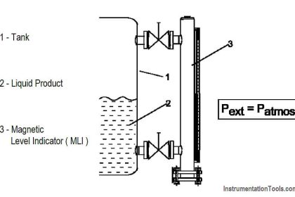
A bridle (or cage, isolating column, bypass pipe, external chamber, etc.) is a vertical pipe connected to the side of a storage tank or process vessel typically with side/side or side/bottom connections.

Because the fluid inside the bridle will rise and fall equally with the level of fluid inside the tank or vessel, the bridle has been adapted for level measurement on a broad scale.

Term “bridle” refers to a bypass chamber on a larger process vessel on which the level instrumentation for that vessel is mounted. Bridles usually do not have level equipment extending into the bridle itself.

Level equipment is typically placed in its own cage or nozzle attached to the bridle.

Oil and Gas Instruments

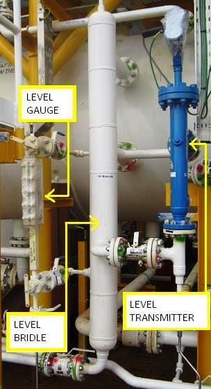
Image Source : instrumentationportal.com

Bridle Advantages

 Tank bridle level measurement has provided industrial users with distinct advantages:

Isolation: Because a level instrument mounted in a bridle is isolated from the process it can be calibrated or maintained without disturbing the process.

Fewer Connections: A bridle reduces the number of connections necessary on the process vessel. This is especially important on boiler code vessels that require qualified welders and procedures.

Prudent Design: Level instrumentation is often the last consideration on a project. Mounting the instrumentation on a bridle eliminates the need for planning multiple instrumentation connections on the vessel.

Saves Time: Because instrumentation is typically left until the end, ordering a bridle with all the level instrumentation cuts down on the time necessary to add connections and install the instrumentation at the project deadline.

Avoids Obstructions: When a tank has mixers, agitators, aerators, ladders, or structural bracing, a bridle avoids any interference between these objects and the level controls.

Reduces Turbulence, Foam: In a highly agitated vessel, a bridle calms the surface to be measured and reduces foam to improve measurement accuracy.

Isolation: Because a level instrument mounted in a bridle is isolated from the process it can be calibrated or maintained without disturbing the process.

Bridle Instruments

Here are a few of the most common level instrument technologies used for tank bridle measurement:

Guided Wave Radar GWR mounted in a cage is well suited for bridle measurement. Configuration is fast and accuracy isn’t affected by changing densities, dielectrics, high temperatures or high pressures.

Magnetic Level Indicators Developed for the most demanding industrial applications, MLIs provide local visual indication and remote indication when combined with a transmitter.

Highly visible flags magnetically coupled to the moving float provide local level indication.

Magnetostrictive Transmitters Designed to attach quickly and easily to magnetic level indicators, magnetostrictive transmitters offer high accuracy and high linearity when combined with MLIs.

External Cage Float Switches A wide range of float switches suitable for bridle applications with flanged and sealed cage designs include ASME B31.1 construction for boiler and power plant use and B31.3 construction for petrochemical use.

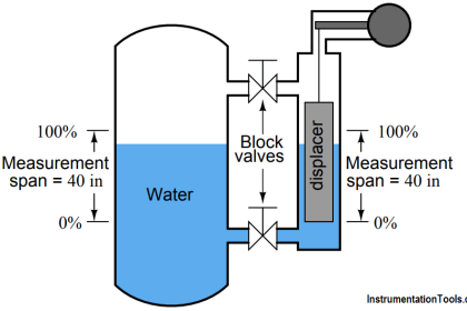
Displacer Controllers Displacer Controllers utilize simple buoyancy principles to detect and convert liquid level changes into a stable output signal.

Modern displacer controllers serve most liquid level measurement and control applications including those with varying dielectric, vapors, turbulence, foam, buildup, bubbling or boiling and high fill/empty rates.

Ultrasonic Contact Point Sensors Nozzle-mounted ultrasonic switches are mounted horizontally on bridles for high or low level alarm applications.

Thermal Dispersion Point Sensors Nozzle-mounted thermal dispersion switches provide a high level of performance for level and interface applications on bridles.

Article Source : magnetrol.com

Image credits : fluidic-ltd.co.uk

Don't Miss Our Updates
Be the first to get exclusive content straight to your email.
We promise not to spam you. You can unsubscribe at any time.
Invalid email address
You've successfully subscribed !

Continue Reading

Open Tank DP Level Transmitter Calibration
Guided Wave Radar – Principle, Limitations, Installation
DP Transmitter Dry Leg & Wet Leg Calculations
Comparison of Level Meters – Level Measurement Instruments
Differential Pressure Transmitters Compensated Leg Systems
Siemens Differential Pressure Transmitter Calculations (Flange Type)
Share This Article
Facebook Whatsapp Whatsapp LinkedIn Copy Link
Share
Leave a Comment

Leave a Reply Cancel reply

Your email address will not be published. Required fields are marked *

Stay Connected

128.3kFollowersLike
69.1kFollowersFollow
208kSubscribersSubscribe
38kFollowersFollow

Categories

Explore More

Purpose of Tank Gauging Level Measurement
Guided Wave Radar Level Sensor Pressure and Temperature Effects
What is Dip Tape Level Measurement?
Basics of DP Transmitter Suppression and Elevation
What is Reflex Level Gauge?
Zero Elevation and Zero Suppression in Level Measurement
How can we use a DP Flow Transmitter for Level Measurement
How to Calculate mmWC Range of Level Transmitter with Examples?

Keep Learning

Bubbler Liquid Level Transmitter Calculation

Bubbler Liquid Level Transmitter Calculation

Capacitive Tank Gauges

Capacitive Tank Gauges

Displacer Level Sensor

What is Displacer Level Sensor ?

Level Measurement in Liquids

Point Level Detection Working Principle

Tilt Level Switch Working Animation

Level Gauges Questions and Answers

Level Gauges Objective Questions and Answers – Instrumentation

Level Sensor Pressure vessel mounting

Level Instruments Design Rules

Probe Type Radar Level Transmitter

Contact Type Guided Wave Radar Level Transmitter Working Principle

Learn More

Electrical Machines Questions and Answers

Induction Motor Phasor Diagram

thin-layer chromatography

Thin-Layer Chromatography : Manual Method

Eddy current Vibration Sensor Principle

Non-contact Vibration Measurement

State Variable Analysis and Design

State Models for Linear Continuous Time Systems

Program to implement T Flip Flop logic

T Flip Flop PLC Ladder Diagram

Emerson ASCO Solenoid valve references

SIS Solenoid Valves – Safety PLC

Instrumentation Engineering Students Test

Instrumentation Engineering Students Test

Structured Text PLC Example for Motor Interlocking and Control

Structured Text PLC Example for Motor Interlocking and Control

Follow US
All rights reserved. Reproduction in whole or in part without written permission is prohibited.
Welcome Back!

Sign in to your account

Username or Email Address
Password

Lost your password?