Inst ToolsInst ToolsInst Tools
  • Courses
  • Automation
    • PLC
    • Control System
    • Safety System
    • Communication
    • Fire & Gas System
  • Instrumentation
    • Design
    • Pressure
    • Temperature
    • Flow
    • Level
    • Vibration
    • Analyzer
    • Control Valve
    • Switch
    • Calibration
    • Erection & Commissioning
  • Interview
    • Instrumentation
    • Electrical
    • Electronics
    • Practical
  • Q&A
    • Instrumentation
    • Control System
    • Electrical
    • Electronics
    • Analog Electronics
    • Digital Electronics
    • Power Electronics
    • Microprocessor
  • Request
Search
  • Books
  • Software
  • Projects
  • Process
  • Tools
  • Basics
  • Formula
  • Power Plant
  • Root Cause Analysis
  • Electrical Basics
  • Animation
  • Standards
  • 4-20 mA Course
  • Siemens PLC Course
Reading: Stilling Wells for Level Measurement
Share
Font ResizerAa
Inst ToolsInst Tools
Font ResizerAa
  • Courses
  • Design
  • PLC
  • Interview
  • Control System
Search
  • Courses
  • Automation
    • PLC
    • Control System
    • Safety System
    • Communication
    • Fire & Gas System
  • Instrumentation
    • Design
    • Pressure
    • Temperature
    • Flow
    • Level
    • Vibration
    • Analyzer
    • Control Valve
    • Switch
    • Calibration
    • Erection & Commissioning
  • Interview
    • Instrumentation
    • Electrical
    • Electronics
    • Practical
  • Q&A
    • Instrumentation
    • Control System
    • Electrical
    • Electronics
    • Analog Electronics
    • Digital Electronics
    • Power Electronics
    • Microprocessor
  • Request
Follow US
All rights reserved. Reproduction in whole or in part without written permission is prohibited.
Inst Tools > Blog > Level Measurement > Stilling Wells for Level Measurement

Stilling Wells for Level Measurement

Last updated: August 16, 2019 6:41 pm
Editorial Staff
Level Measurement
No Comments
Share
4 Min Read
SHARE

Disturbances in the liquid tend to complicate liquid level measurement. These disturbances may result from liquid introduced into a vessel above the liquid level (splashing into the liquid’s surface), the rotation of agitator paddles, and/or turbulent flows from mixing pumps.

Any source of turbulence for the liquid surface (or liquid-liquid interface) is especially problematic for echo-type level sensors, which only sense interfaces between vapors and liquids, or liquids and liquids.

If it is not possible to eliminate disturbances inside the process vessel, a relatively simple accessory one may add to the process vessel is a vertical length of pipe called a stilling well.

To understand the principle of a stilling well, first consider the application of a hydraulic oil reservoir where we wish to continuously measure oil level.

The oil flow in and out of this reservoir will cause problems for the displacer element:

liquid level measurement

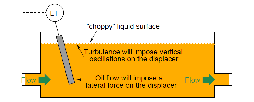
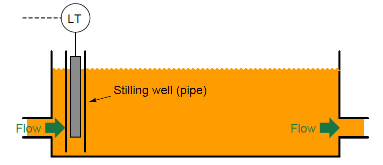
A section of vertical pipe installed in the reservoir around the displacer will serve as a shield to all the turbulence in the rest of the reservoir.

The displacer element will no longer be subject to a horizontal blast of oil entering the reservoir, nor any wave action to make it bob up and down.

This section of pipe quiets, or stills, the oil surrounding the displacer, making it easier to measure oil level:

stilling well in level measurement

Stilling wells may be used in conjunction with many types of level instruments: floats, displacers, ultrasonic, radar, and laser to name a few.

If the process application necessitates liquid-liquid interface measurement, however, the stilling well must be properly installed to ensure the interface level inside the well match the interface levels in the rest of the vessel.

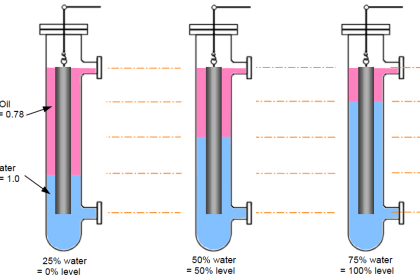
Consider this example of using a stilling well in conjunction with a tape-and-float system for interface measurement:

Stilling wells

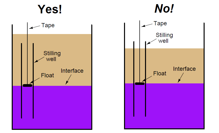
In the left-hand installation where the stilling well is completely submerged, the interface levels will always match.

In the right-hand installation where the top of the stilling well extends above the total liquid level, however, the two levels may not always match.

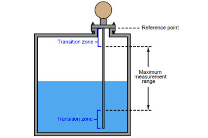
This potential problem for the non-submerged stilling well is graphically illustrated here:

Level Transmitter Stilling wells

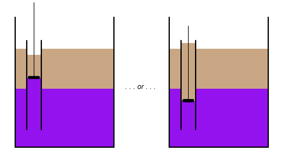
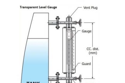
The problem here is analogous to what we see with sightglass-style level gauges: interfaces may be reliably indicated if and only if both ends of the sightglass are submerged ( for an illustrated explanation of the problem, check this Article CLICK HERE ).

If it is not possible or practical to ensure complete submersion of the stilling well, an alternative technique is to drill holes or cut slots in the well to allow interface levels to equalize inside and outside of the well tube:

Stilling well

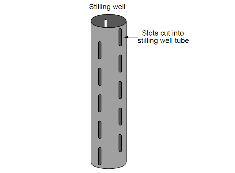
Such equalization ports are commonly found as a standard design feature on coaxial probes for guided-wave radar level transmitters, where the outer tube of the coaxial transmission line acts as a sort of stilling well for the fluid.

Coaxial probes are typically chosen for liquid-liquid interface radar measurement applications because they do the best job of preventing dispersion of the electromagnetic wave energy, but the “stilling well” property of a coaxial probe practically necessitates these equalization ports to ensure the interface level within the probe always matches the interface level in the rest of the vessel.

Credits : Tony R. Kuphaldt – Creative Commons Attribution 4.0 License

Don't Miss Our Updates
Be the first to get exclusive content straight to your email.
We promise not to spam you. You can unsubscribe at any time.
Invalid email address
You've successfully subscribed !

Continue Reading

DP Transmitter Interface Level Measurement Principle, Limitations, Selection, Installation, Design & Calibration
Air Purge or Air Bubbler Level Measurement
Radar Level Measurement
Open Tank Level Measurement using DP Transmitter
Level Indicators Working Principle
Effects of Symmetric and Asymmetric Capillary Tube Pressure Measurement
Share This Article
Facebook Whatsapp Whatsapp LinkedIn Copy Link
Share
Leave a Comment

Leave a Reply Cancel reply

Your email address will not be published. Required fields are marked *

Stay Connected

128.3kFollowersLike
69.1kFollowersFollow
210kSubscribersSubscribe
38kFollowersFollow

Categories

Explore More

Effect of Temperature & Pressure on Level Measurement
Open Tank DP Level Transmitter Calibration
DP Level Transmitter Auto Calibration
Drum Level Compensation and Range Calculation of DP Transmitter
Root Cause Analysis of Differential Pressure Level Transmitter
Effect of Tank Design on Accuracy of Level Measurement
Paddle Wheel Level Switch Principle
Radar and Ultrasonic Level Transmitter Practical Problems Troubleshooting

Keep Learning

Displacer Level Measurement Formula

Displacer Level Measurement Calculations

Ultrasonic Level Switch Principle

Ultrasonic Level Switch Principle

Servo Tank Gauge Level Principle

Servo Tank Gauges Working Principle

Questions on Level Switches

Questions on Level Switches

Level Sensor Pressure vessel mounting

Level Instruments Design Rules

How Buoyant Force instruments Works

How Buoyant Force instruments Works ?

Guided-wave Radar Level Measurement Animation

How a Level Switch Works

Learn More

Digital Electronics Objective Questions

Digital Electronics Objective Questions – Set 6

Air Consumption Calculation for Control Valves

Air Consumption Calculation for ON/OFF Valves

Time Response Analysis

Design Considerations for Higher Order Systems

How to Use Analog Input in Mitsubishi FX3U LOLLETTE PLC

How to Use Analog Input in Mitsubishi FX3U LOLLETTE PLC?

Introduction to Protective Systems

Introduction to Protective Systems

Flanged pipe fittings

What is Flanged Pipe Fittings ?

Control Panels Material Take-Off (MTO)

Control Panels Material Take-Off (MTO) – Engineering Project

Cable Float Level Switch Principle

Cable Float Level Switch Working Principle

Menu

  • About
  • Privacy Policy
  • Copyright

Quick Links

  • Learn PLC
  • Helping Hand
  • Part Time Job

YouTube Subscribe

Follow US
All rights reserved. Reproduction in whole or in part without written permission is prohibited.
Welcome Back!

Sign in to your account

Username or Email Address
Password

Lost your password?