Measurement principle
The Magnetic Level Indicator (MLI) is a simple, rugged instrument designed to indicate level or interface. It indicates level using a float magnetically coupled to an index or a column of rotating flaps. It is ideal for aggressive media stored in vessels when the PTFE lining option is used.
The float is equipped with a ring system of permanent magnets for transmission of liquid level to the indicator. The indicator is linked magnetically to the magnet system in the float.
For the purpose of design, the minimum level in the measuring tube is given by the lower lateral flange connection axis i.e. liquid level zero is the centreline of the lower connecting flange.
Magnetic level Indicators (MLI) are preferred Level Indicator (compared with glass or reflex indicators) because of safer performance against external explosions and high pressure application.
There is a difference between the true liquid level and the indicator position because:
- the float is immersed to a certain depth depending on the product density and float type
- the float magnets are positioned below the float centreline in order for the float to have good stability.
The scale is delivered correctly set up for measuring the product specified in the order. The red reference mark at the top of the measuring tube (item 1 in the diagram below) shows where the top of the scale should be clamped for the indicator to give an accurate reading of liquid level. No further adjustment is necessary when the gauge is commissioned.
Notes:
1. If there is a large change in product density, a product other than the one specified in the order is measured or a different float is installed, the scale on the MLI may require adjusting to give an accurate reading.
2. Magnetostrictive Level Transmitter may be considered for giving the capability to transmit a level measurement signal remotely.
Limitations
If the user wishes to use the MLI to measure another product, then the following points should be noted:
- the depth of immersion of the float increases as product density decreases. This depth is also dependent on the float model and material used (AISI 316L, AISI 316Ti or titanium)
- the top of the float should be no more than 35 mm above the product surface to ensure reliable floatability and accurate measurement
- ensure that the float and chamber are designed according to the design pressure and temperature.
The chamber should be regularly drained down to prevent the build‐up of debris and cleaned. Floats should be inspected to ensure they are not damaged, corroded or pitted. The rotating flaps should be lubricated and checked, as often they can stick causing an incorrect and misleading level.
Selection
MLI should be suitable for interface level measurement if specific gravities differ significantly and the change in specific gravity due to composition or temperature cannot affect the reading. It is allowed that the difference between specific gravities is greater than 0.1.
MLI instruments should not be used in severely turbulent, dirty, foaming, fouling service or in case of presence of solid particles in the fluid (e.g. sand). These conditions lead to unreliable measurements from displacement level instruments.
MLI should not be used for liquid‐liquid interfaces when the two fluids form an important emulsion (above a few centimetres) or do not have a clean interface.
MLI should not be used in liquid‐liquid or liquid–gaseous services where either the upper or lower fluid specific gravity is not relatively constant.
Design
MLI should be made of stainless steel or other material compatible with the process fluid.
MLI should have the height according to the level range for the application. The range of measurement is the C‐C length.
Floats are selected in accordance with the liquid density.
Installation
The installation should be reviewed and any requirements for trace heating or insulation incorporated in to the design and installation of the measuring tube.
Operating procedures should prevent rapid pressurization of the float chamber. Damage and failure of the float can occur if the chamber is pressurized quickly. The float can be rammed to one end of the chamber.
Float stops should be provided at both ends of the chamber. (This requirement from ATEX applications, typically fabricated using a high quality spring fitted with a carbon or PTFE buffer, depending on design process conditions.)
Mechanical installation requirements
The effective pressure of the installation (the maximum permitted by the pressure limiting valve) should never be greater than the maximum permitted pressure Ps of the instrument nameplate.
The application should be compatible with the fluid and conform to ageing characteristics of the fluid used and the measurement environment.
The external pressure (Pext) should be equal to atmospheric pressure (Patmos).

Figure – MLI Mechanical installation requirement
Mounting on the vessel
The chamber/cage level indicator should be installed vertically on the vessel.
When installing the chamber/cage level indicator with or without the electrical level transducer system, make sure that any magnetic fields generated by other equipment will not affect measurements.
Selected bolts and gaskets should correspond to the pressure rating of the connecting flange and the operating pressure. The process connections (flanges) should fit properly, i.e. they should be centred, parallel and bolted in a professional way, in order to avoid unnecessary mechanical stress on the installation.
The vessel should be free of contaminants. It is recommended to install isolation and vent/drain elements, e.g. cocks, valves, etc. between the vessel and chamber/cage level indicator to allow the chamber/cage level indicator to be cleaned independently of the vessel. The drain plug in the bottom flange should also be replaced by a drainage cock with discharge line.
Calibration and configuration
Calibration should be performed at product manufacturer premises and verified prior to the commissioning activities.
Correcting the scale position to accurately read true liquid level (Process conditions changes).
The scale* can be corrected using the following procedure:
Steps
1. Find the float immersion depth “c”
2. Subtract the dimension “a”, float base to magnet centreline (given on the float dimensioned, from “c” to get the dimension “b”, scale correction factor.
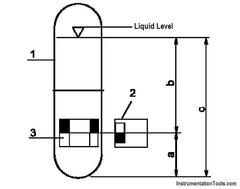
Where,
- b = c – a (difference between liquid level and indicator position due to product density)
- c = float immersion depth (a function of product density)
- a = distance from centreline of magnet system to the float base
- 1 = Float
- 2 = Follower magnet of indicator (or limit switch)
- 3 = Position of magnets mounted in the float
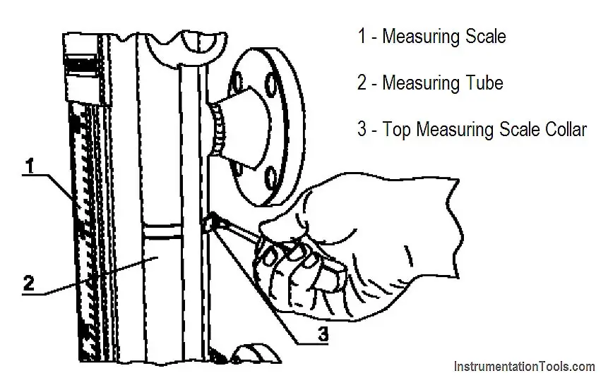
3. Loosen the two clamp collars holding the measuring scale onto the measuring tube using a screwdriver or 8 mm wrench.
4. Bring the zero point on the scale into line with the centreline of the bottom lateral process connection.
5. Undo top collar
Source : International Association of Oil & Gas Producers
Acknowledgements : IOGP Instrumentation and Automaton Standards Subcommittee (IASSC), BG Group, BP, Endress + Hauser, Emerson, Honeywell, Krohne, Petrobras, PETRONAS Carigali Sdn Bhd, Repsol, Siemens, Statoil, Total, Vega, Yokogawa.


When installed in two magnetic level gauge is vessel/tank. What is distance between one magnetic level gauge to another magnetic level gauge? Why?
Any Answer???