Radar level measurement are two types Pulsed Radar and Frequency Modulated Continuous Wave (FMCW) Radar. Read complete Guided Wave Radar Questions and Answers.
Guided Wave Radar Questions
Contacting Radar Questions
What is the principle of operation of Guided Wave Radar ?
Radar level measurement technology can be broken down into two different categories; Pulsed and Frequency Modulated Continuous Wave (FMCW).
An advantage with Pulsed Technology is that it requires less processing power. Therefore most two-wire gauges use this technology.
An advantage with FMCW is that higher accuracy can be achieved but more processing power is required and therefore FMCW-radars are typically four-wire.
In Pulsed transmitters the level measurement is a function of the time taken from the radar signal to travel to the surface and back.
In FMCW gauges the transmitter constantly emits a swept frequency and the distance is calculated by the difference in frequency of emitted and received signal.
Are radar gauges safe?
Yes. The emitted signal is less than three percent of maximum leakage allowed from a microwave oven. Radar waves are of no greater intensity than the constant radio, cellular and other communication waves that surround us every day.
Furthermore the transmitter is normally placed in a metallic tank that acts as a Faraday’s cage and therefore the radar waves are isolated within the tank.
What is the difference in frequency between Pulsed Technology Guided Wave Radar and Non Contacting Radar?
With Guided Wave Radar the pulsed microwave are guided down the tank by the probe, making it less sensitive to disturbances than free propagating microwaves.
Pulsed Non Contacting Radar uses a carrier frequency, e.g. 6 Hz or 26 Hz, to carry the microwave which are radiated into the tank with an antenna.
Why should we use radar technology?
The radar signal is virtually unaffected by the tank content and tank atmosphere, temperature or pressure. The measurement is not influenced by changing material characteristics such as density, dielectric properties and viscosity.
Since there are no moving parts the transmitters are virtually maintenance free. All of the characteristics above make radar a very useful and fast growing level measurement technology.
How does the frequency of the radar affect the measurement?
A higher frequency provides a more concentrated narrow beam which can be useful in applications where there are obstacles present in the tank such as man-ways, agitators or heating coils.
The downside of high frequency is that the measurement is more affected by vapours, dust and product build up on the antenna, Low frequency radar which have a longer wavelength and wider beam angle, tends to cope better with steam, dust, condensation, contamination and turbulent surfaces.
In what way does the dielectric constant (DC) of the media affect the measurement?
Electromagnetic energy is emitted from all radar devices. When the emitted signal reaches a point where there is a change in DC, usually the media surface, some of the signal is reflected back to the transmitter.
The amount of energy that is reflected back to the transmitter is proportional to the DC of the media. A rule-of-thumb is that the value of the dielectric constant represents the percentage of energy that is reflected.
Thus a DC of eight means that eight percent of the emitted energy is reflected back to the transmitter. Fundamentally media with a higher DC provide stronger return signals and are therefore easier to measure.
Does Radar work on foam?
The effects of foam on a radar measurement can be difficult to predict. In some applications the foam may dampen out the signal completely while other types of foam may be transparent to the transmitter.
The thickness, density and the dielectric constant are factors that need to be considered when evaluating an application with foam.
On dry foam the microwaves typically passes through and detects the liquid surface below. On medium type foam the signal can be absorbed or scattered and the results are therefore hard to predict.
If the foam is wet the microwaves are often reflected from the foam surface and thereby the foam surface level is measured.
The frequency at which the radar operates also affects how fowm is measured. Low ferquency radar (5 GHz) in general penetrates foam to a larger extent than high frequency (20 GHz) radar.
Guided Wave Radar is in general better suited to measure on applications where foam is present, since the radar uses a lower frequency pulse.
Are there any restrictions on what still-pipe material can be used?
Any type of conductive material can be used as long as it is compatible with the process media.
If the material is not conductive it will be transparent to the radar-beams and therefore it will have no affect.
Will two or more radar units in one vessel conflict with each other?
The signals from two or more transmitters in one tank will not blend and therefore the radar units will not conflict with each other.
If it concerns two or more 3300s the rules for nearby objects would apply to the probes as they do to other metallic objects nearby. For that reason the probes need to be installed a certain distance away from each other.
Will radio noise or other interference cause problems?
The transmitters use a specific narrow frequency and are therefore not prone to disturbances from other sources.
It is very uncommon with disturbances and it is rare that the disturbance source operates at precisely the same frequency as the transmitter.
Furthermore, the transmitters are often installed in metallic tanks that provide a Faraday’s cage which prevents electromagnetic disturbances from the outside to enter the tank. With Guided Wave Radar, if disturbances are present in tank the coaxial probe are recommended, since the radar signal travels inside of the pipe undisturbed by the interference sources on the outside.
Are there any restrictions on the nozzle height?
Since the nozzle, and especially the lower end of the nozzle, can create interfering echoes it is recommended that the height of the nozzle is kept within certain values depending on the type of probe / antenna and type of transmitter that is used.
For detailed information regarding these values please refer to the Product Data Sheet and Reference Manual for each transmitter.
Are there any restrictions on the nozzle diameter?
In conjunction with the above statement, the nozzle diameter also affects the measurement.
since a diameter nozzle that is too small will create disturbance echoes.
For detailed information regarding these values please refer to the Product Data Sheet and Reference Manual for each transmitter.
Are there any restrictions when measuring in stilling pipes?
Pipes should be an all-metal material. Non-metallic pipes or sections are not recommended for non-contacting radar.
Plastic, plexiglas, or other non-metal materials do not shield the radar from outside disturbances and offer minimal, if any, application benefit.
Other requirements include:
- Pipe should have a constant inside diameter
- Pipe must be smooth on the inside (smooth pipe joints are acceptable, but may reduce accuracy)
- Avoid deposits, rust, gaps and slots
- One hole above the product surface
- Minimum hole diameter is 0.25 in. (6 mm)
- Hole diameter (Ø) should not exceed 10% of the pipe diameter (D)
- Minimum distance between holes is 6 in. (150 mm) (1)
- Holes should be drilled on one side and de-burred
- Ball valve or other full valves must be completely open
Failure to follow these requirements may affect the reliability of the level measurement.
What is purpose of exotic materials?
In some applications with high temperatures, or in highly corrosive environment, the probes or antennas need to be made out of exotic materials that can be stand the material stress.
Two different exotic materials as standards: Alloy 400 C-276
What is EDDL & DD’S? and how do they affect configuration tools and host systems?
Basic configuration can easily be done either with Rosemount RadarMaster, a Rosemount 375 Field Communicator, the AMS™ Suite, DeltaV® or any other DD (Device Description) compatible host system.
For advanced configuration features and extensive diagnostics, RadarMaster, or an alternative host that supports enhanced EDDL (such as the AMS Device Manager) is required.
Rosemount RadarMaster is shipped with every transmitter but it is also possible to download RadarMaster or other DD’s on Rosemount.com RadarMaster is a user-friendly, Widnows based software package that provides easy configuration and service for both FOUDATION™ filedbus and HART®.
A wizard guides the user to enter the required parameters for a basic configuration. “Measure & learn” functionality is accessed through Radarmaster. It enables automatic suggestion of level threshold values, therebymaking tough applications easy to configure.
RadarMaster also includes an echo curve with movie featur, off-line configuration, logging and extensive on-line help. The Enhanced EDDL capabilities of the Rosemount Radars also make it possible to view the echo curve from a field communicator or AMS, and to initiate the Measure-and-Learn functionality in the transmitter.
How to interpret the electrical distance in the tank plot in Radar Configuration Tools (RCT) and Rosemount Radar Master(RRM)?
The electrical distance that is shown on the x-axis of the tank plot is used when comparing the distance measured by the transmitter and the real distance.
Due to the influence from the dielectric properties on the wave propagation speed the electrical distance values have to be adjusted when the wave is not traveling through air.
The electrical length shows the distance with the assumption that the wave travels in air. Practically this means that the distance to the first level peak will have the same electrical distance and real distance.
When the waves continues down through the media the real length from the surface to the end of the probe or to the interface level can be calculated through the formula below:
![]()
In conclusion the distance to the upper product can be read straight from the plot while the interface distance has to be calculated using the formulae above.
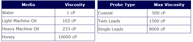
How viscous can the measured media be?
The different probes have different max limits regarding the viscosity of the measured media.
The single probes are more suitable for high viscosity media while the coax probe can be used on low viscosity media.
The guidelines for the different probes and examples of viscosity are presented below:
How will coating affect the measurement?
If coating forms on the probe the measured signal will be weaker. If the media itself has a high dielectric constant some coating is not much concern but if it is a low DC media coating can be a problem.
If a twin probe or a coaxial probe is used the coating can cause bridging between the two leads and this will create false echoes that can lead the transmitter to interpret a bridge as the actual level.
Single lead is recommended in coating applications. Coating can cause an accuracy influence. Maximum error due to coating is 1-10% depending on probe type, dielectric constant, coating thickness and coating height above product surface.
What are the special considerations for interface measurement?
For interface measurement a few criteria have to be fulfilled:
- The dielectric of the upper product must be known and should not vary.
- Upper product dielectric < Lower product dielectric
- Difference between dielectrics depends on the upper product thickness, but a guideline is > 10(3300) > 6(5300)
- Thickness of upper product > 10 cm (4 in.) for coax, rigid twin and rigid single probes and 20 cm (8 in) for flexible twin probes in order to be detected
- The max measuring range is limited by the upper product dielectric constant
- Coaxial, Twin probes or rigid single can be used
- Max upper product DC is 5 for twin lead probes and 10 for coaxial probe
Target applications include interfaces between oil/oil-like (DC < 3) and water/water-like liquids (DC > 20). Consult factory regarding other interface applications and when emulsion layer!
Can Guided Wave Radar measure emulsion layers?
Emulsion layers are in general hard to predict and there are three main types of layers:
DC of top layer and emulsion layer is similar (difference in dielectric constant < 10). In this case the interface level as reported by the transmitter will be the bottom of the emulsion layer.
DC of bottom layer and emulsion layer is similar (difference in dielectric constant between top layer and emulsion layer > 10). In this case the interface level as reported by the transmitter will be the top of the emulsion layer.
There is a linear transition in DC from the bottom to the top of the emulsion layer. In this case it is hard to predict where the reported interface level is. If the linear transition is over a long distance there is a risk that no interface echo is reflected back to the transmitter.
since the reflecting pulse is created when there is a distinct change in DC. If a linear oil water interface is very thin (< 10 cm) the transmitter would probably give a good signal from the interface since the emulsion is so thin and the difference in dielectrics between oil and water is large.
It is difficult to say though where the transmitter will report the interface level. It can report the top of, the bottom of, or somewhere within, the emulsion layer.
Will the Guided Wave Radar see sand in the bottom of a vessel?
No. Since the sand will be embedded in water which is a high dielectric media (DC~80) the transmitter will only see the water.
The same is true for all media that are embedded in water.
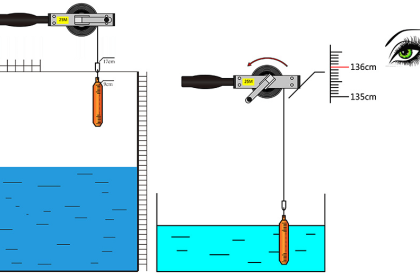
Is there any inactive part of the probe?
The active measuring range is reduced by the upper and lower dead zones. The upper dead zone is the minimum distance from the reference point to the product surface.
The measuring range is also reduced in the end of the probe by the lower dead zone.
How large the upper and lower dead zones are depend on probe type and the dielectric constant of the measured media.
How close to the tank wall can the probe be mounted?
Like the nozzle the tank wall can also affect the measurement through disturbance echoes.
The minimum distance to the tank wall is the same as the distance to any disturbing object that may be present in the tank.
If there are obstacles present in the tank the coaxial probe is the best probe to use. If the tank wall is metallic and smooth the probe can be mounted closer to the wall.
What are the special considerations when measuring ammonia?
Tanks with anhydrous ammonia have a heavy vapor above the surface that attenuates the signal from the radar transmitter. A higher pressure in the tank will cause a more attenuated signal.
A special formula is therefore used to evaluate what the maximum measuring range is in anhydrous ammonia as a function of the pressure in the tank:
![]()
Note that, when measuring hydrous (aqueous) ammonia, this formula does not apply.
What pull force will break a flexible single lead probe?
In solid application, media might cause down-pull forces on silo roofs. The silo roof must be able to withstand the probe collapse load or at least the maximum probe tensile load.
The tensile load depends on the silo size, material density, and the friction coefficient. Forces increase with the buried length, the silo and probe diameter.
In critical cases, such as for products with a riskfor build-up, it is better to use a 0.24 in (6 mm) probe.
Depending on their position, forces on probes are generally two or ten times greater on probes with tie-down than on probes with ballast weights.
What measurement error will an incorrect dielectric constant cause in on an interface level?
Errors due to changes in the medium’s dielectric values can be significant. It is calculated by:
![]()
For example, if the physical thickness is 20” (51 cm) and dielectric varies from 2 to 4:
E = ( 20/sqrt(2) ) – ( 20/sqrt(4) ) = 4.14″ = 11 cm
Non Contacting Radar Questions
What is the principle of operation for non contacting radars?
FMCW technology transmitter constantly emits a swept frequency signal and the distance is calculated by the difference in frequency between the emitted and received signal at any point in time.
One advantage with FMCW is that higher accuracy can be achieved. For more general information regarding the principle operation please refer to What is the principle of operation under General Questions.
The Pulsed Radar transmitter is a free propagating radar. The level of the liquid is measured by short radar pulses which are transmitted from the antenna at the tank top towards the liquid.
When a radar pulse reaches a media with a different dielectric constant, part of the energy is reflected back to the transmitter.
The time difference between the transmitted and the reflected pulse is proportional to the distance, from which the level is calculated.
How close to the tank wall can the non contacting transmitter be mounted?
The minimum distance to the tank wall depends on which antenna is used. With a more concentrated beam (larger antenna), the closer to the tank wall the device can be mounted.
What are the special considerations when measuring ammonia?
Tanks with anhydrous ammonia have a heavy vapor above the surface that attenuates the signal from the radar transmitter. A higher pressure in the tank will cause a more attenuated signal.
A special formula is therefore used to evaluate what the maximum measuring range is in anhydrous ammonia as a function of the pressure in the tank. For the 5600 the formula is:
Max Measuring Range (m) = 20 / Pressure in Bar
Note that, when measuring hydrous (aqueous) ammonia, this formula does not apply. Hydrous ammonia has a high dielectric constant and therefore provides good reflection.
Are there any special considerations when installing non contacting radars in a still-pipe?
Installing in a still-pipe can be used either when the existing tank connection includes a stilling well or when the measurement is improved by measuring inside a pipe instead of outside.
The cone antenna is used for still-pipe measurements and it is important that the size of the antenna match the size of the pipe.
For optimal accuracy the inside of the pipe must be clean and free from deposit, rust, gaps ,slots etc. The largest pipe / antenna that can be used is 6″.
For larger diameter pipes the 5600 Series should not be used. For more detailed information on measurement in still-pipes.
Why do you use process seal antennas?
To isolate electronics from process in tank such as vapour and corrosion. The Process Seal antenna has a PTFE window. It is an all PTFE antenna (all materials exposed to tank atmosphere are PTFE).
Due to the smooth surface of the window and the non-sticky nature of PTFE it can be used on some hygienic applications.
What is the difference between a cone and a horn antenna?
It is just different names for the same type of antenna.
Article Source : emersonprocess


sir, what is difference b/w X purging system & environmental purging system
becoz of that first client requirement is X purging system But after some day client to us plz refer instrument Environmental purging Systems . we confuse about it .we know X,Y& Z purging,according Class Area,Group,Division Zone (Ratings) for Hazards Solution. plz give me better solution ,what want our client.(Refinery field client)
Thanking You Sir….
& Sir tell me in brief in about Environmental purging System…
Please write about Bundled Waveguide Ultrasonic Transducers for flow measurement of High temperature applications.