Level Measurement
Liquid level measuring devices are classified into two groups: (a) direct method, and (b) inferred method. An example of the direct method is the dipstick in your car which measures the height of the oil in the oil pan. An example of the inferred method is a pressure gauge at the bottom of a tank which measures the hydrostatic head pressure from the height of the liquid.
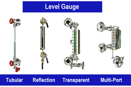
Level Gauge
A very simple means by which liquid level is measured in a vessel is by the gauge glass method (Figure 1). In the gauge glass method, a transparent tube is attached to the bottom and top (top connection not needed in a tank open to atmosphere) of the tank that is monitored. The height of the liquid in the tube will be equal to the height of water in the tank.
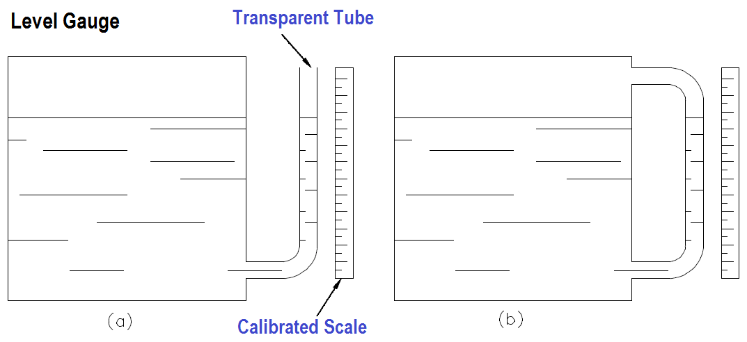
Figure 1 Transparent Tube
Figure 1 (a) shows a gauge glass which is used for vessels where the liquid is at ambient temperature and pressure conditions. Figure 1 (b) shows a gauge glass which is used for vessels where the liquid is at an elevated pressure or a partial vacuum. Notice that the gauge glasses in Figure 1 effectively form a “U” tube manometer where the liquid seeks its own level due to the pressure of the liquid in the vessel.
Transparent Level Gauge
Gauge glasses made from tubular glass or plastic are used for service up to 450 psig and 400°F. If it is desired to measure the level of a vessel at higher temperatures and pressures, a different type of gauge glass is used. The type of gauge glass utilized in this instance has a body made of metal with a heavy glass or quartz section for visual observation of the liquid level. The glass section is usually flat to provide strength and safety. Figure 2 illustrates a typical transparent gauge glass.
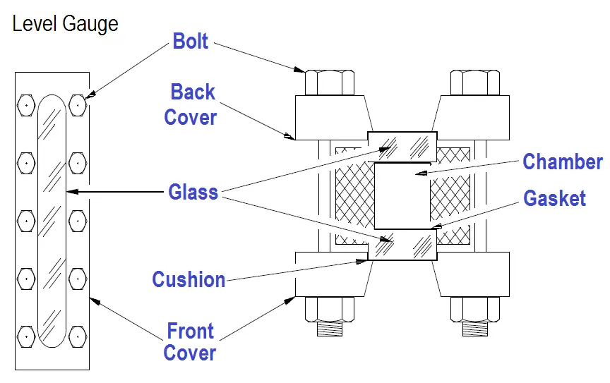
Figure 2 Gauge Glass
Reflex Level Gauge
Another type of gauge glass is the reflex gauge glass (Figure 3). In this type, one side of the glass section is prism-shaped. The glass is molded such that one side has 90-degree angles which run lengthwise. Light rays strike the outer surface of the glass at a 90-degree angle. The light rays travel through the glass striking the inner side of the glass at a 45-degree angle. The presence or absence of liquid in the chamber determines if the light rays are refracted into the chamber or reflected back to the outer surface of the glass.
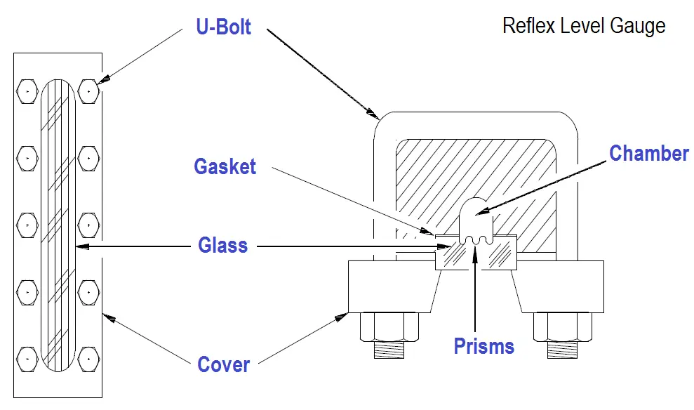
Figure 3 Reflex Gauge Glass
When the liquid is at an intermediate level in the gauge glass, the light rays encounter an air-glass interface in one portion of the chamber and a water-glass interface in the other portion of the chamber. Where an air-glass interface exists, the light rays are reflected back to the outer surface of the glass since the critical angle for light to pass from air to glass is 42 degrees. This causes the gauge glass to appear silvery-white. In the portion of the chamber with the water-glass interface, the light is refracted into the chamber by the prisms. Reflection of the light back to the outer surface of the gauge glass does not occur because the critical angle for light to pass from glass to water is 62-degrees. This results in the glass appearing black, since it is possible to see through the water to the walls of the chamber which are painted black.
Radiation Level Gauge
A third type of gauge glass is the refraction type (Figure 4). This type is especially useful in areas of reduced lighting; lights are usually attached to the gauge glass. Operation is based on the principle that the bending of light, or refraction, will be different as light passes through various media. Light is bent, or refracted, to a greater extent in water than in steam. For the portion of the chamber that contains steam, the light rays travel relatively straight, and the red lens is illuminated. For the portion of the chamber that contains water, the light rays are bent, causing the green lens to be illuminated. The portion of the gauge containing water appears green; the portion of the gauge from that level upward appears red.
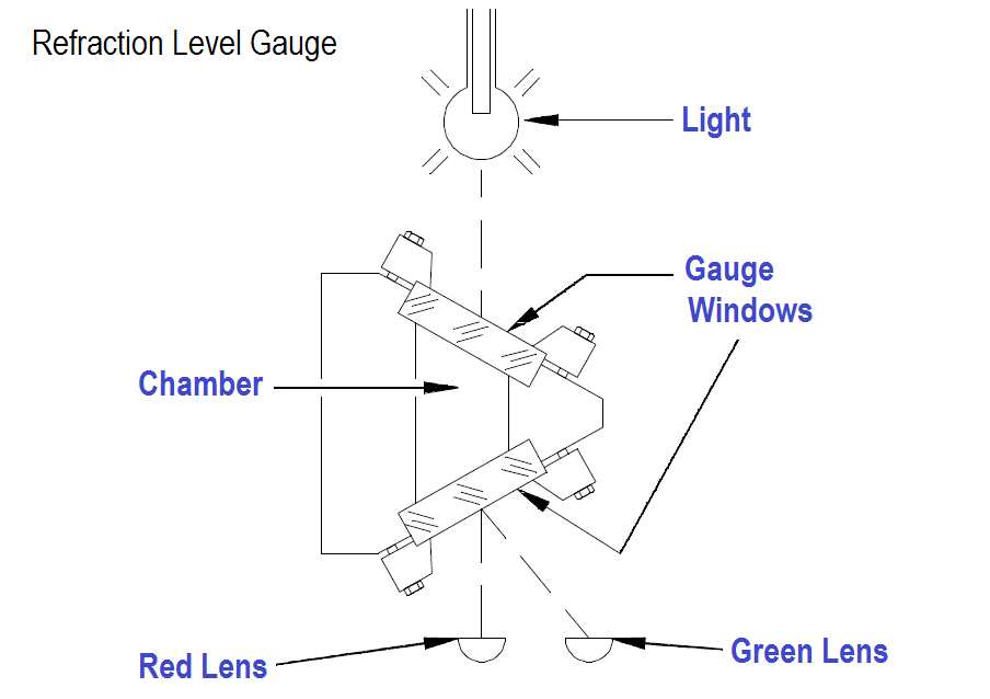
Figure 4 Refraction Level Gauge
Ball Float Level Gauge
The ball float method is a direct reading liquid level mechanism. The most practical design for the float is a hollow metal ball or sphere. However, there are no restrictions to the size, shape, or material used. The design consists of a ball float attached to a rod, which in turn is connected to a rotating shaft which indicates level on a calibrated scale (Figure 5). The operation of the ball float is simple. The ball floats on top of the liquid in the tank. If the liquid level changes, the float will follow and change the position of the pointer attached to the rotating shaft.
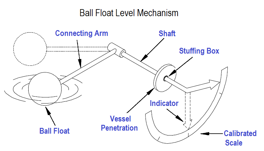
Figure 5 Ball Float Level Mechanism
The travel of the ball float is limited by its design to be within ±30 degrees from the horizontal plane which results in optimum response and performance. The actual level range is determined by the length of the connecting arm.
The stuffing box is incorporated to form a water-tight seal around the shaft to prevent leakage from the vessel.
Chain Float Level Gauge
This type of float gauge has a float ranging in size up to 12 inches in diameter and is used where small level limitations imposed by ball floats must be exceeded. The range of level measured will be limited only by the size of the vessel. The operation of the chain float is similiar to the ball float except in the method of positioning the pointer and in its connection to the position indication. The float is connected to a rotating element by a chain with a weight attached to the other end to provide a means of keeping the chain taut during changes in level (Figure 6).
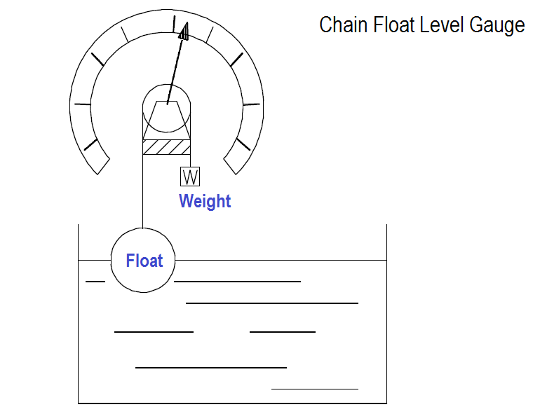
Figure 6 Chain Float Level Gauge Principle
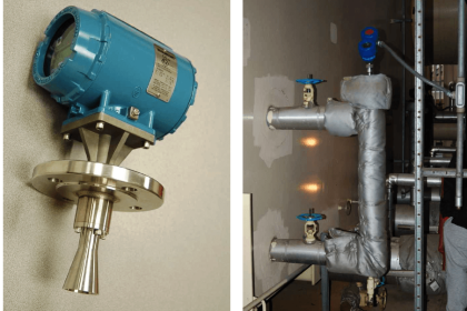
Magnetic Bond Method
The magnetic bond method was developed to overcome the problems of cages and stuffing boxes. The magnetic bond mechanism consists of a magnetic float which rises and falls with changes in level. The float travels outside of a non-magnetic tube which houses an inner magnet connected to a level indicator. When the float rises and falls, the outer magnet will attract the inner magnet, causing the inner magnet to follow the level within the vessel (Figure 7).
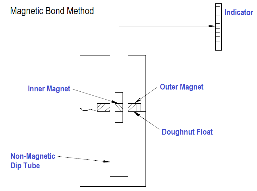
Figure 7 Magnetic Bond Detector
Conductivity Probe Method
Figure 8 illustrates a conductivity probe level detection system. It consists of one or more level detectors, an operating relay, and a controller. When the liquid makes contact with any of the electrodes, an electric current will flow between the electrode and ground. The current energizes a relay which causes the relay contacts to open or close depending on the state of the process involved. The relay in turn will actuate an alarm, a pump, a control valve, or all three. A typical system has three probes: a low level probe, a high level probe, and a high level alarm probe.
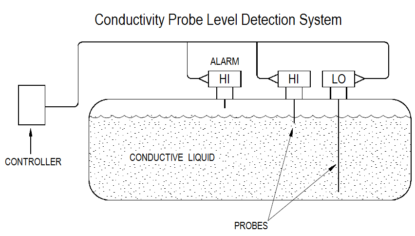
Figure 8 : Conductivity Probe Level Detection System
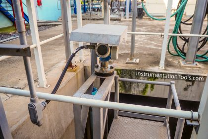
Differential Pressure Level Sensors
The differential pressure (DP) sensor/detector method of liquid level measurement uses a DP detector connected to the bottom of the tank being monitored. The higher pressure, caused by the fluid in the tank, is compared to a lower reference pressure (usually atmospheric). This comparison takes place in the DP detector. Figure 9 illustrates a typical differential pressure detector attached to an open tank.
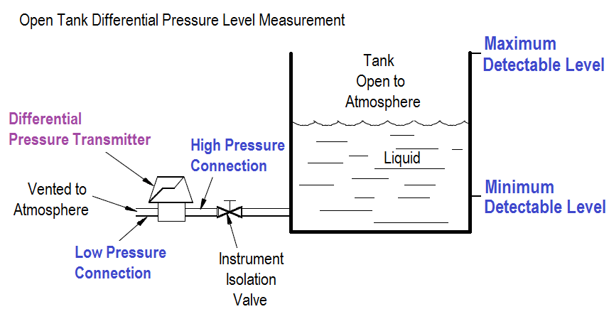
Figure 9 Open Tank Differential Pressure Level Measurement
The tank is open to the atmosphere; therefore, it is necessary to use only the high pressure (HP) connection on the DP transmitter. The low pressure (LP) side is vented to the atmosphere; therefore, the pressure differential is the hydrostatic head, or weight, of the liquid in the tank. The maximum level that can be measured by the DP transmitter is determined by the maximum height of liquid above the transmitter. The minimum level that can be measured is determined by the point where the transmitter is connected to the tank.
Not all tanks or vessels are open to the atmosphere. Many are totally enclosed to prevent vapors or steam from escaping, or to allow pressurizing the contents of the tank. When measuring the level in a tank that is pressurized, or the level that can become pressurized by vapor pressure from the liquid, both the high pressure and low pressure sides of the DP transmitter must be connected (Figure 10).
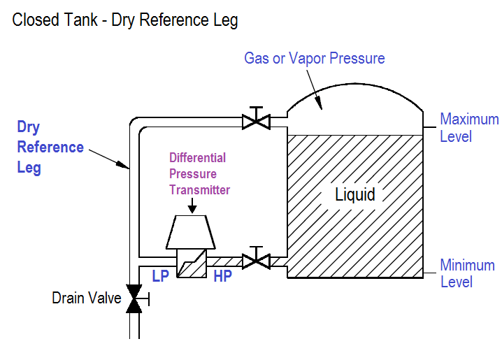
Figure 10 Closed Tank, Dry Reference Leg
The high pressure connection is connected to the tank at or below the lower range value to be measured. The low pressure side is connected to a “reference leg” that is connected at or above the upper range value to be measured. The reference leg is pressurized by the gas or vapor pressure, but no liquid is permitted to remain in the reference leg. The reference leg must be maintained dry so that there is no liquid head pressure on the low pressure side of the transmitter. The high pressure side is exposed to the hydrostatic head of the liquid plus the gas or vapor pressure exerted on the liquid’s surface. The gas or vapor pressure is equally applied to the low and high pressure sides. Therefore, the output of the DP transmitter is directly proportional to the hydrostatic head pressure, that is, the level in the tank.
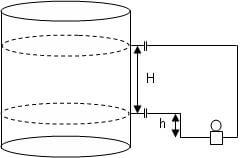
Where the tank contains a condensible fluid, such as steam, a slightly different arrangement is used. In applications with condensible fluids, condensation is greatly increased in the reference leg. To compensate for this effect, the reference leg is filled with the same fluid as the tank. The liquid in the reference leg applies a hydrostatic head to the high pressure side of the transmitter, and the value of this level is constant as long as the reference leg is maintained full. If this pressure remains constant, any change in DP is due to a change on the low pressure side of the transmitter (Figure 11).
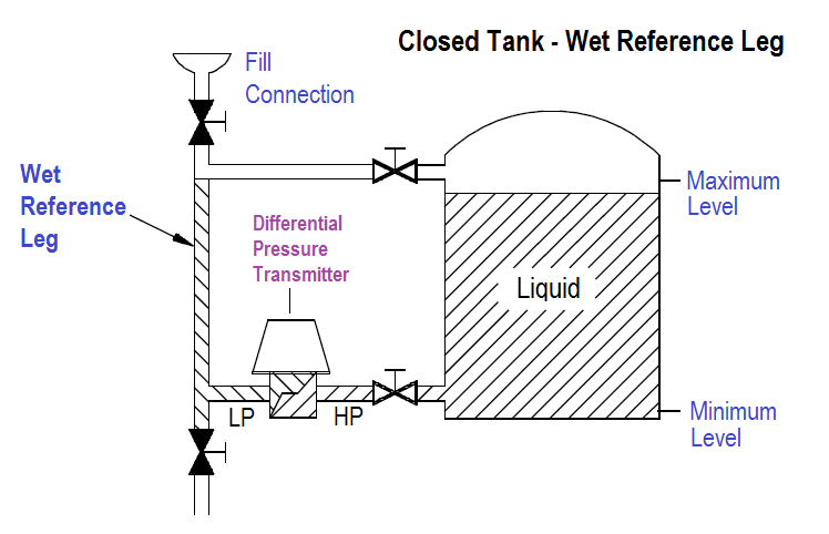
Figure 11 Closed Tank, Wet Reference Leg
The filled reference leg applies a hydrostatic pressure to the high pressure side of the transmitter, which is equal to the maximum level to be measured. The DP transmitter is exposed to equal pressure on the high and low pressure sides when the liquid level is at its maximum; therefore, the differential pressure is zero. As the tank level goes down, the pressure applied to the low pressure side goes down also, and the differential pressure increases. As a result, the differential pressure and the transmitter output are inversely proportional to the tank level.


Hi sir,
Please tell me a dry leg and wet leg formula
I once had a level indicator that used a lite fluid to register what the oil-level was on my car’s engine, using a tube down the dip stick tube to the small block on the dash. The level of the oil entering the tube in the oil pan pushed air in the tube to the block with the lite fluid and indicated how high it would be on the stick. It was flawless but it went with the car when I sold it.
I have a different application I’d like to find a similar device for.