Learn the water fountain control logic using the PLC timers programming to control the high and low spray modes.
Please note that this PLC programming example is provided for educational purposes and allows learners to go through the practical usage of ladder logics.
Water Fountain Control Logic
Problem Statement:
Design a PLC ladder logic for the following application.
We are using one toggle switch to control High-Spray and Low-Spray.
The water fountain should operate in three stages or modes, as mentioned below.
- High Spray for 15 seconds.
- Low Spray for 10 seconds.
- OFF for 5 seconds.
PLC Exercises and Solutions
These PLC exercises and solutions offer you the opportunity to learn the programming with in-depth concepts.
This PLC video helps you to understand the water fountain program.
Inputs and Outputs
Digital Inputs:
Start Button: I0.0
Digital Outputs:
High Spray: Q0.0
Low Spray: Q0.1
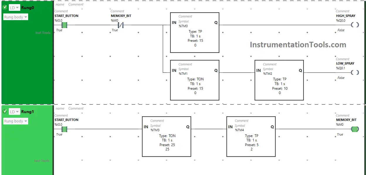
Ladder Diagram
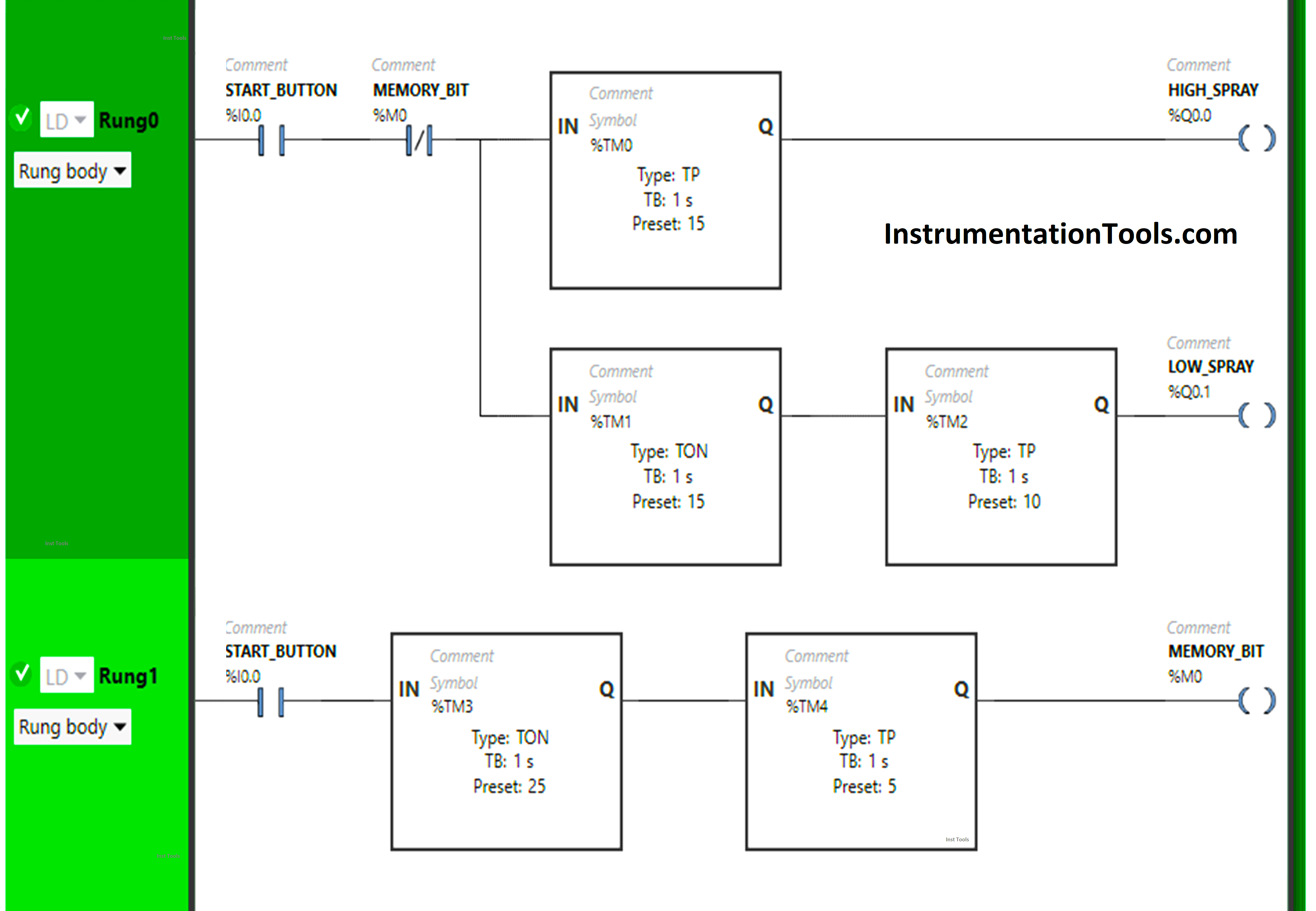
Program Description
We have used Normally Open Contact for the Start Button (I0.0).
We have used Normally Closed Contact for Memory Bit (M0).
In Rung 0:
- Normally Open Contact is used for the Start Button (I0.0) to Turn ON the outputs High Spray (Q0.0) and Low Spray (Q0.1).
- Normally Closed Contact is used for Memory Bit (M0) to Turn OFF the outputs High Spray (Q0.0) and Low Spray (Q0.1).
- Timer-type TP is used to Turn ON the output High Spray (Q0.0) for a limited time.
- Timer-type TON is used to delay the turning ON time of the output Low Spray (Q0.1) for some time.
- Timer-type TP is used to Turn ON the output Low Spray (Q0.1) for a limited time.
In Rung 1:
- Normally Open Contact is used for the Start Button (I0.0) to Turn ON Memory Bit (M0).
- Timer-type TON is used to delay the turning ON time of Memory Bit (M0) for some time.
- Timer-type TP is used to Turn ON the Memory Bit (M0) for a limited time.
PLC Result
Now we will simulate the PLC logic and discuss the results.
Rung 0:
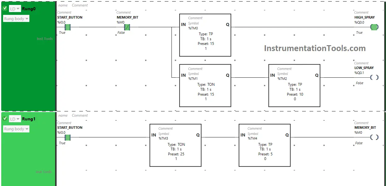
When the Start Button (I0.0) is turned ON, the output High Spray (Q0.0) will turn ON for 15 seconds as Timer Function Block type TP is used to Turn ON the output High Spray (Q0.0) for a limited time. The time is set to 15 seconds.
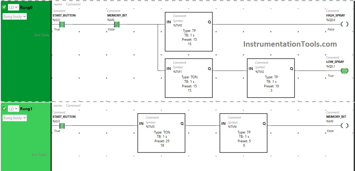
After 15 seconds, the output High Spray (Q0.0) will turn OFF. Also, when the Start Button (I0.0) is turned ON, the output Low Spray (Q0.1) will turn ON after 15 seconds, (i.e immediately when the output High Spray (Q0.0) turns OFF) as Timer Function Block TON is used to delay the turning ON time of the output Low Spray (Q0.1). The time is set to 15 seconds.
After 15 seconds, the Low Spray (Q0.1) will turn ON but only for 10 seconds as Timer Function Block type TP is used to Turn ON the output Low Spray (Q0.1) for limited time. The time is set to 10 seconds. After 10 seconds, the output Low Spray (Q0.1) will turn OFF.
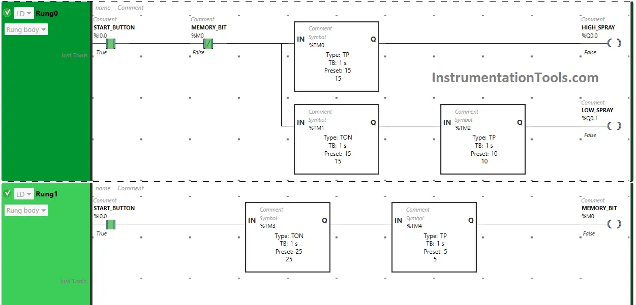
Rung 1:
When the Start Button (I0.0) is turned ON, the Memory Bit (M0) will turn ON after 25 seconds (i.e immediately when the output Low Spray (Q0.1) turns OFF) as Timer Function Block TON is used to delay the turning ON time of Memory Bit (M0). The time is set to 25 seconds.
After 25 seconds, Memory Bit (M0) will turn ON but only for 5 seconds as Timer Function Block type TP is used to Turn ON Memory Bit (M0) for a limited time. The time is set to 5 seconds. After 5 seconds, Memory Bit (M0) will turn OFF.
When Memory Bit (M0) turns ON in Rung1, Normally Closed Contact used for Memory Bit (M0) in Rung0 i.e used to turn OFF both outputs High Spray (Q0.0) and Low Spray (Q0.1) will be in True state and does not allow signal to pass to the outputs High Spray (Q0.0) and Low Spray (Q0.1) and the outputs High Spray (Q0.0) and Low Spray (Q0.1) will turn OFF.
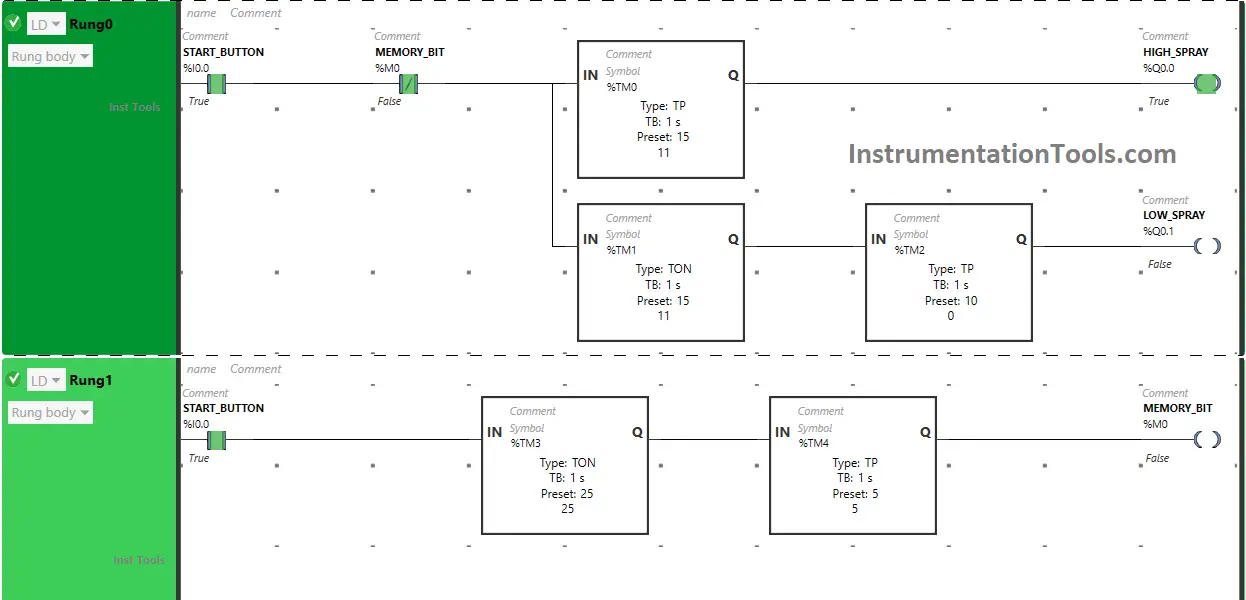
When the timer reaches its set time in Timer Function Block type TP in Rung1, Memory Bit (M0) turns OFF. When Memory Bit (M0) turns OFF in Rung1, Normally Closed Contact used for Memory Bit (M0) in Rung0 will be in a false state and will allow the signal to pass to the outputs High Spray (Q0.0) and Low Spray (Q0.1) and the outputs High Spray (Q0.0) and Low Spray (Q0.1) will turn ON again.
If you liked this article, please subscribe to our YouTube Channel for PLC and SCADA video tutorials.
You can also follow us on Facebook and Twitter to receive daily updates.
Read Next:
- PLC Logic for Stairway Lighting
- Data Sharing Between PLC Systems
- PLC Programming for Barrier Control
- Traffic Lights PLC Logic using Timers
- Control Spray Nozzle, Fans, Puncher


Hi my name is Anwar fountain worker