Inst ToolsInst ToolsInst Tools
  • Courses
  • Automation
    • PLC
    • Control System
    • Safety System
    • Communication
    • Fire & Gas System
  • Instrumentation
    • Design
    • Pressure
    • Temperature
    • Flow
    • Level
    • Vibration
    • Analyzer
    • Control Valve
    • Switch
    • Calibration
    • Erection & Commissioning
  • Interview
    • Instrumentation
    • Electrical
    • Electronics
    • Practical
  • Q&A
    • Instrumentation
    • Control System
    • Electrical
    • Electronics
    • Analog Electronics
    • Digital Electronics
    • Power Electronics
    • Microprocessor
  • Request
Search
  • Books
  • Software
  • Projects
  • Process
  • Tools
  • Basics
  • Formula
  • Power Plant
  • Root Cause Analysis
  • Electrical Basics
  • Animation
  • Standards
  • 4-20 mA Course
  • Siemens PLC Course
Reading: Understanding Braking Theory in VFD
Share
Notification Show More
Font ResizerAa
Inst ToolsInst Tools
Font ResizerAa
  • Courses
  • Design
  • PLC
  • Interview
  • Control System
Search
  • Courses
  • Automation
    • PLC
    • Control System
    • Safety System
    • Communication
    • Fire & Gas System
  • Instrumentation
    • Design
    • Pressure
    • Temperature
    • Flow
    • Level
    • Vibration
    • Analyzer
    • Control Valve
    • Switch
    • Calibration
    • Erection & Commissioning
  • Interview
    • Instrumentation
    • Electrical
    • Electronics
    • Practical
  • Q&A
    • Instrumentation
    • Control System
    • Electrical
    • Electronics
    • Analog Electronics
    • Digital Electronics
    • Power Electronics
    • Microprocessor
  • Request
Follow US
All rights reserved. Reproduction in whole or in part without written permission is prohibited.
Inst Tools > Blog > Electrical Basics > Understanding Braking Theory in VFD

Understanding Braking Theory in VFD

In this post, we will see the braking theory and logic used in a variable frequency drive (VFD) for proper control of a motor.

Last updated: September 28, 2022 4:14 pm
Viral Nagda
Electrical Basics PLC Tutorials
No Comments
Share
7 Min Read
SHARE

In this post, we will see the brake logic used in a VFD.

Contents
Braking Theory in VFDBrake release frequencyBrake engage frequencyBrake engage delayBrake engage timeBrake release timeBrake logic outputCurrent ramp time (Brake release)

We all know that braking is nothing but a force that is applied to stop a movement. This logic is also used in VFD for proper control of a motor.

As we know, a VFD will drive the variable speed motor where it is used in the system. There are some applications where the load of the motor is such that it will move the motor without any command given to it.

Braking Theory in VFD

Variable speed drive inverter converter

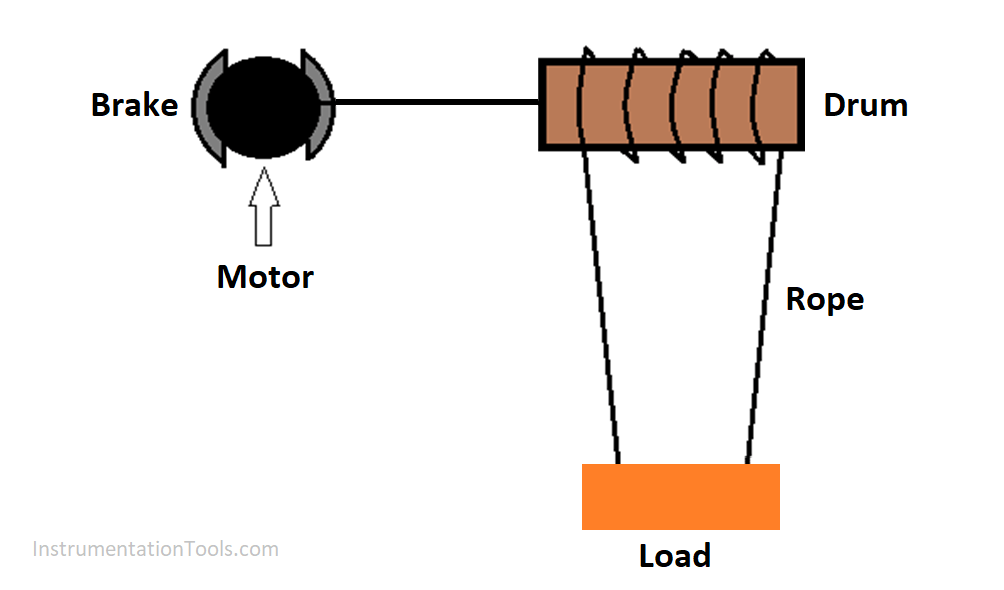
Consider a hoisting system below. It is nothing but a hoist that is used to lift and drop loads; which you may have seen in under-construction buildings or factories.

The motor, driven by VFD, is used to rotate a drum which has ropes entangled on it to lift or drop a load as the drum rotates. Now, if the motor is in stop condition and consider a case where electromagnetic brakes are not available.

Due to heavy presence of load on the drum side, the gravitational force and the drum will cause the motor to rotate even if the motor is in stop condition.  

This can cause serious damage to personnel standing below the hoist or can collide with any nearby object in the environment.

Understanding Braking Theory in VFD

To avoid this, mechanical brakes are used along with the motor to hold it in stop condition. The torque and force applied by it will be such that it can overcome the gravitational force and the heavy load of the system.

Normally, a mechanical spring force in combination with a friction disk is used to provide the holding torque. An electromagnet is used to overcome the spring force to allow the friction disk, which is connected to the motor shaft, to spin freely.

A contactor is used in the electrical panel to operate the brake output. This contactor is controlled by VFD output. That means related programming is done in VFD to control this brake output.

Programming is related to engagement (brake applied) and release (brake released) parameters. It is done to properly operate the brake with respect to motor.

If there is any malfunction in the sequence of operation of both the brake and motor movement, it can result in wear and tear of the components in the long-time run. This can cause degradation of the braking torque.

So, appropriate programming of the parameters is required in VFD related to brake logic. We will have a look at the most generally used parameters that do the controlling part.

Brake release frequency

This is the frequency at which the motor will run when brakes are released. It runs only for a specified time.

After this, the VFD will start ramping up. This provides sufficient torque to hold the motor without movement, equal to the static torque of load.

Brake engage frequency

This is the frequency at which the motor will run when brakes are engaged. It runs only for a specified time after ramp-down has started and reached this frequency.

After this, VFD will move to zero frequency. This provides sufficient torque to hold the motor without movement, equal to the static torque of load.

Brake engage delay

This is the delay after which brakes will be engaged.

Brake engage time

This is the time for which the motor runs at brake engage frequency with brakes engaged. After this, the VFD moves towards zero frequency.

Brake release time

This is the time for which the motor runs at brake release frequency with brakes released. After this, the VFD starts to ramp up.

Brake logic output

You need to assign a VFD digital output which will be connected to the brake contactor in the panel.

Current ramp time (Brake release)

This is the time for which current reaches equal to a set threshold value (starting current), after which brake is released. This time is allowed for magnetic flux to build up in the air gap of the motor.

Now, let us look at the flow of logic sequence. As soon as VFD run command is given, the current ramp time starts to allow the motor to reach brake release frequency.

As soon as this frequency is reached, brake contactor (brake logic output from VFD) goes off to release the brake and the motor runs at brake release frequency.

It will run like this for the set brake release time. After this time, the VFD starts ramping up towards the desired frequency set in VFD.

When stop command is given, the VFD starts ramping down towards brake engage frequency. Once this frequency is reached, brake engage delay time starts.

After this time, the brake contactor goes on to engage the brake, but the motor will still run at the brake engage frequency for brake engage time. After this time, the VFD will ramp towards zero frequency.

Due to all this control, it is ensured that the motor is operating in tandem with mechanical brakes for an efficient and safe operation.

Commissioning of such systems requires a sound knowledge of VFD parameters and motor working. Or else, it can damage the system.

Author: Viral Nagda

If you liked this article, then please subscribe to our YouTube Channel for Instrumentation, Electrical, PLC and SCADA video tutorials.

You can also follow us on Facebook and Twitter to receive daily updates.

Read Next:

  • Basic of a Safety Relay
  • Analog and Digital Signals
  • Building Management System
  • Control Multiple Motors with VFD
  • Isolators & Barriers in Electrical Panel
Don't Miss Our Updates
Be the first to get exclusive content straight to your email.
We promise not to spam you. You can unsubscribe at any time.
Invalid email address
You've successfully subscribed !

Continue Reading

1 to 8 Demultiplexer PLC ladder diagram
MCB vs Fuse Questions and Answers
3 to 8 Line Decoder PLC Ladder Diagram
How to Solve Electrical Ground Loop Problems?
Step by Step Guidelines for Downloading Free PLC software
Design a Program Using Studio 5000 and FactoryTalk View Studio
Share This Article
Facebook Whatsapp Whatsapp LinkedIn Copy Link
Share
Leave a Comment

Leave a Reply Cancel reply

Your email address will not be published. Required fields are marked *

Stay Connected

128.3kFollowersLike
69.1kFollowersFollow
210kSubscribersSubscribe
38kFollowersFollow

Categories

Explore More

Top 100+ SCADA Questions
PLC Analog Signals Wiring Techniques
Top 10 Common Mistakes on Electrical Systems
Steps in PLC System Design
PLC Program to Count Running Hours of any Equipment
PLC Program for Temperature Control using Thermostat
Dynamic Braking Resistor in VFD
#6 PLC Best Practices – Validate Timers and Counters

Keep Learning

Master Control Reset (MCR) ladder logic

How to use Master Control Reset (MCR) Instruction in PLC

Siemens PLC

Will PLCs become obsolete?

Lights with Adjustable Timers PLC Programming

Flip-Flop PLC Programming: Lights with Adjustable Timers

HMI

Learn about SCADA and HMI Systems

PLC Ladder Diagram program

Contacts and Coils in PLC Ladder Logic

Introduction to Protective Systems

Introduction to Protective Systems

PLC Ladder Logic Simulator Mobile Apps For Android

PLC Ladder Logic Simulator Mobile Apps For Android

PLC Question Bank

PLC Question Bank

Learn More

PLC Program for Burglar Alarm Security System

PLC Program for Alarm Security System

Control Valve Plug Stem and Gland Leaks

Repeat Control Valve Plug Stem and Gland Leaks

PLC Cabinet

PLC Programming Videos

Electric Circuits Objective Questions

Electric Circuits Objective Questions – Set 5

Process Control Automation PLC Quiz

Process Control Automation PLC Quiz

Emergency Shutdown Button Installation (ESD)

Understanding Emergency Shutdown Button Installation (ESD)

Partial Stroke Testing Device (PSD) in SIS Final Control Element

Partial Stroke Testing Device (PSD) in SIS Final Control Element

Manometer Measures Differential Pressure

How Manometer Measures Differential Pressure for Different Fluids?

Menu

  • About
  • Privacy Policy
  • Copyright

Quick Links

  • Learn PLC
  • Helping Hand
  • Part Time Job

YouTube Subscribe

Follow US
All rights reserved. Reproduction in whole or in part without written permission is prohibited.
Welcome Back!

Sign in to your account

Username or Email Address
Password

Lost your password?