Inst ToolsInst ToolsInst Tools
  • Courses
  • Automation
    • PLC
    • Control System
    • Safety System
    • Communication
    • Fire & Gas System
  • Instrumentation
    • Design
    • Pressure
    • Temperature
    • Flow
    • Level
    • Vibration
    • Analyzer
    • Control Valve
    • Switch
    • Calibration
    • Erection & Commissioning
  • Interview
    • Instrumentation
    • Electrical
    • Electronics
    • Practical
  • Q&A
    • Instrumentation
    • Control System
    • Electrical
    • Electronics
    • Analog Electronics
    • Digital Electronics
    • Power Electronics
    • Microprocessor
  • Request
Search
  • Books
  • Software
  • Projects
  • Process
  • Tools
  • Basics
  • Formula
  • Power Plant
  • Root Cause Analysis
  • Electrical Basics
  • Animation
  • Standards
  • 4-20 mA Course
  • Siemens PLC Course
Reading: Relative Flow Capacity of a Valve
Share
Font ResizerAa
Inst ToolsInst Tools
Font ResizerAa
  • Courses
  • Design
  • PLC
  • Interview
  • Control System
Search
  • Courses
  • Automation
    • PLC
    • Control System
    • Safety System
    • Communication
    • Fire & Gas System
  • Instrumentation
    • Design
    • Pressure
    • Temperature
    • Flow
    • Level
    • Vibration
    • Analyzer
    • Control Valve
    • Switch
    • Calibration
    • Erection & Commissioning
  • Interview
    • Instrumentation
    • Electrical
    • Electronics
    • Practical
  • Q&A
    • Instrumentation
    • Control System
    • Electrical
    • Electronics
    • Analog Electronics
    • Digital Electronics
    • Power Electronics
    • Microprocessor
  • Request
Follow US
All rights reserved. Reproduction in whole or in part without written permission is prohibited.
Inst Tools > Blog > Control Valves > Relative Flow Capacity of a Valve

Relative Flow Capacity of a Valve

Last updated: March 21, 2019 4:08 pm
Editorial Staff
Control Valves
1 Comment
Share
5 Min Read
SHARE

The flow capacity of a valve (Cv) is a quantitative rating of its ability to pass a fluid flow for a set of given pressure and fluid density conditions, defined as the flow rate of water in gallons per minute through the valve given a constant pressure drop of 1 PSID.

Cv may be predicted, or empirically measured, for any type of control valve given the proper information.

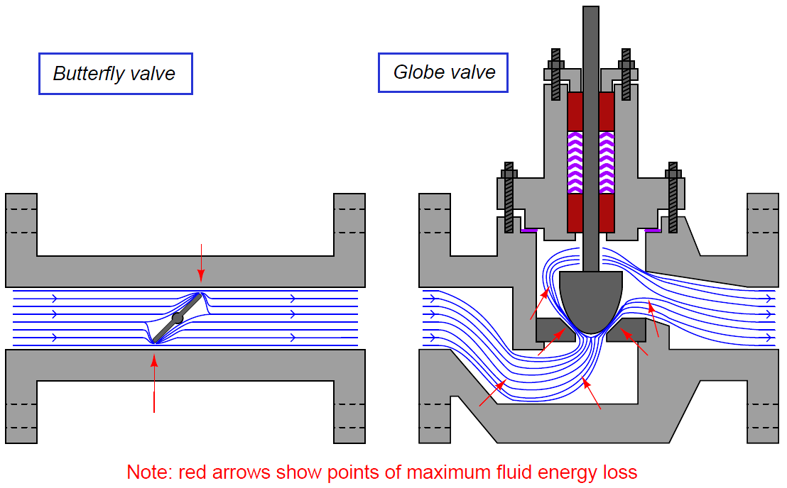
Not all control valve types exhibit the same Cv coefficients, however, for the same pipe size. A 4 inch butterfly valve, for example, has a much greater full-open Cv rating than a 4 inch globe valve, due to the much more direct path it offers to a moving fluid.

Relative Flow Capacity of a Valve

A simple comparison of these two valve types clearly shows why this is true (note the “constriction” points labeled with arrows):
Relative Flow Capacity of a Valve

A globe valve is simply more effective at generating fluid turbulence – and therefore dissipating fluid kinetic energy – than a butterfly valve of the same pipe size, because the globe valve design forces the fluid to change direction more often and in different ways.

One way to help quantify a particular valve design’s ability to throttle fluid flow is to express this ability as a ratio of flow coefficient (Cv) versus cross-sectional pipe area.

The basic principle here is that we should expect the Cv of any particular valve design to be proportional to pipe area (e.g. a ball valve with twice the pipe area should have twice the flow capacity, all other factors being equal), and therefore a ratio of these two quantities should be fairly constant for any valve design.

Since we know the area of a pipe is proportional to the square of either radius or diameter (A = πd2/ 4 or A = πr2), we may simplify this ratio by omitting all constants such as π and simply relating Cv factor to the square of pipe diameter (d2). This ratio is called the relative flow capacity, or Cd:

relative flow capacity

Several approximate valve capacity factors (Cd) for different control valve types are shown here, assuming full-area (not reduced-port) trim, a wide-open position, and diameter measured in inches:
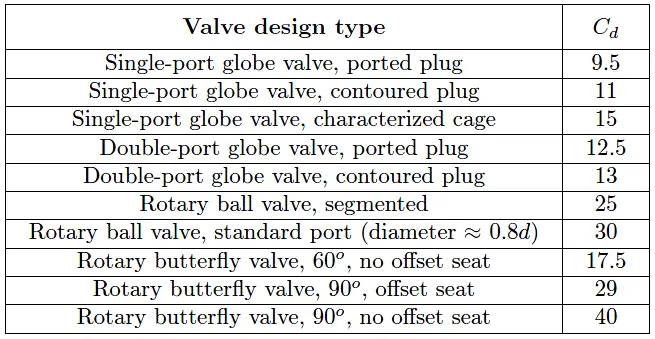
different control valve types design

To calculate the approximate Cv for any valve, all we need to do is square that valve’s pipe diameter (in inches) and multiply by the valve type’s relative flow capacity (Cd):

Cv ≈ d2Cd

Based on the figures in this table, for example, we may predict that a segmented ball valve with a pipe size of 3 inches will have a flow capacity (Cv) of approximately 225, or that a single-port cage-guided globe valve with an 8 inch pipe size will have a Cv of approximately 960.

As you can see from a comparison of Cd values, a no-offset butterfly valve has nearly 4 times the flow capacity of a single-ported contoured-plug globe valve of the same pipe size (Cd = 40 versus Cd = 11).

This makes butterfly valves advantageous in applications where large flow capacities must be achieved at minimal cost, such as in air handling (HVAC) systems for commercial buildings and combustion air controls for large industrial burners.

At first glance this may seem to make larger Cd valve types the superior choice for control valve applications, yielding the greatest Cv values for the smallest pipe sizes.

However, there are other factors to consider such as ease of maintenance, noise and cavitation abatement, characterization, and valve seat leakage.

For these reasons some of the lowest-Cd valve types (e.g. globe valves) remain popular choices for industrial control applications even though they require larger pipe sizes to achieve the same amount of flow compared to other valve types (e.g. ball valves).

Also Read : Types of Valve Actuators

Don't Miss Our Updates
Be the first to get exclusive content straight to your email.
We promise not to spam you. You can unsubscribe at any time.
Invalid email address
You've successfully subscribed !

Continue Reading

Control Valve Volume Booster Working Principle
Electro Pneumatic Valve Positioner Schematic & Principle
Control Valve Packing
What is Lift Check Valve ?
Shaft and Coupling Bore Tapers Repair Caused Frequent Shutdowns
Valve Safety Factor
Share This Article
Facebook Whatsapp Whatsapp LinkedIn Copy Link
Share
1 Comment
  • Enrique says:
    May 29, 2019 at 2:34 am

    I’am a little confused about the relative flow coefficient of a valve as described above.Is “d” a valve nominal diameter or the pipe diameter as cited “simply relating Cv factor to the square of pipe diameter (d2)”?Thanks for your reply

    Reply

Leave a Reply Cancel reply

Your email address will not be published. Required fields are marked *

Stay Connected

128.3kFollowersLike
69.1kFollowersFollow
210kSubscribersSubscribe
38kFollowersFollow

Categories

Explore More

Applications of Needle Valves
Cavitation Test Setup
 Control Valve Accessories – Principle, Purpose, Advantages
What is Swing Check Valve ?
How Ball Valves Work ?
Air Pressure Regulator Questions
Effect of Differential Pressure on Control Valve Lift
Valve Materials Comparison Notes

Keep Learning

What is Cavitation

What is Cavitation? What are the Causes?

Control Valve in Nutshell - Valve Design and Selection Factors

Control Valve in Nutshell – Valve Design and Selection Factors

Control Valves Pre-Commissioning Checklist

Control Valves Pre-Commissioning Checklist

Valve Sequencing

Complementary Control Valve Sequence

Globe Valve Disk and Stem Connections

Globe Valve Seat and Disk

Control Valve Testing for Noise Measurement

Control Valve Testing for Noise Measurement

How Valve Positioners act as Cascade Control Systems in a Loop?

How Valve Positioners act as Cascade Control Systems in a Loop?

What is a Servo Valve?

What is a Servo Valve? – Principle and Advantages

Learn More

Auto-negotiation in Network

What is Auto-negotiation in Network?

Argonite Fire Suppression System Animation

Argonite Fire Suppression System Working Principle

Why is IGBT used in VFD

Why is IGBT used in VFD?

Digital Electronics MCQ

Digital Integrated Circuits Objective Questions – Part 1

Thermowell Problems

Thermowell Problems

On Delay Timer using PLC

ON Delay Timer using PLC

Edge Detection in PLC

Edge Detection in PLC Programming

Digital Electronics Multiple Choice Questions

Random Access Memory Objective Questions – Part 3

Menu

  • About
  • Privacy Policy
  • Copyright

Quick Links

  • Learn PLC
  • Helping Hand
  • Part Time Job

YouTube Subscribe

Follow US
All rights reserved. Reproduction in whole or in part without written permission is prohibited.
Welcome Back!

Sign in to your account

Username or Email Address
Password

Lost your password?