Star and delta are the two basic three-phase connections. A star connection is a 4 wire system, whereas a Delta connection is a 3 wire system.
Star-delta connection is one type of starting method of 3 phase AC induction motor. Normally starter is used for the smooth starting of a motor. Star-delta starter starts the motor by reducing the initial current.
Initially, the motor is connected to the start of the connection. A little sometime afterward, the motor is connected to a delta connection.
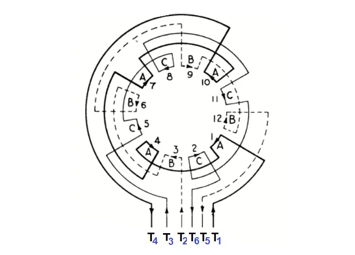
3 Phase Motor Connections
The 3 phases of a 3-phase winding can be connected in two different ways as per the figure shown below.
Star Connection
In the star connection, either the start or all the finish ends of the three windings are connected together.
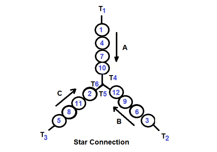
The ends of the three phases T4, T5, and T6 can be connected together at a common point called the “neutral point” leaving the phase beginnings as leads. This is shown schematically in the Figure below. This kind of connection is the star or wye connection because the schematic diagram of this connection resembles the letter Y.
Instead of connecting the ends of the phases to the neutral, the beginnings of the phases T1, T2, and T3 can be connected together leaving the ends T4, T5, and T6 as leads.
Hence, the star (wye) connection of the 3 phases is obtained, when either the beginnings or the ends of the 3 phases are connected together and the 3, not connected wires are used as leads.
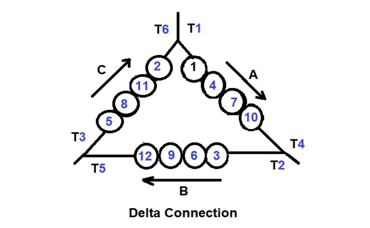
Delta Connection
The Delta connection is so named because it appears like the Greek letter. To make the delta connection, the end of the first winding is connected to the start of the second winding, the end of the second winding is connected to the start of the third winding, and the end of the third winding is connected to the start of the first winding
The figure above shows schematically the delta connection of the 3 phases. Here the end of phase A (T4) is connected with the beginnings of phase B (T2), the end of phase B (T5) is connected with the beginning of phase C (T3), and the end of phase C (T6) is connected with the beginning of phase A (T1).
The leads are connected to all three corners of the triangle. The delta connection can also be obtained if the end of phase A (T4) is connected with the beginning of phase C (T3); the end of phase C (T6) connected with the beginning of phase B (T2), and the end of phase B (T5) with the beginning of phase A (T1).
In a balanced Star-connected network the following points are worth noting:
- Line voltages are root 3 times the phase voltages
- Line currents are equal to phase currents.
- Line voltages are 120 degrees apart.
- Line voltages are 30 degrees ahead of the respective phase voltages.
In a delta connection, the dissimilar ends of the three-phase windings are joined together.
Since in delta only one phase is included between any pair of line outers, therefore the potential difference between the line outers called the line voltages and is equal to phase voltage.
Line voltage = Phase voltage.
In the case of the Delta connection system, the following points are worth noting.
- Line voltages are equal to phase voltages.
- Line currents are root 3-time phase currents.
- Line currents are 120 degrees apart.
- Line currents are 30 degrees behind their respective phase currents.
When we use Star and Delta?
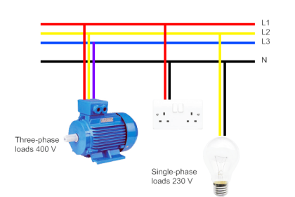
When it is needed more current and a neutral point, the star connection is practiced but when high voltage is concerned then delta is used.
Generally, we use the star connection with neutral for distribution and the delta for transmission.
Reference: Winding Alternating – Current Machines by Michael Liwschitz- Garik.
If you liked this article, then please subscribe to our YouTube Channel for Instrumentation, Electrical, PLC, and SCADA video tutorials.
You can also follow us on Facebook and Twitter to receive daily updates.
Read Next:


I have read and understood what i asked for.thank u for your answering me