Inst ToolsInst ToolsInst Tools
  • Courses
  • Automation
    • PLC
    • Control System
    • Safety System
    • Communication
    • Fire & Gas System
  • Instrumentation
    • Design
    • Pressure
    • Temperature
    • Flow
    • Level
    • Vibration
    • Analyzer
    • Control Valve
    • Switch
    • Calibration
    • Erection & Commissioning
  • Interview
    • Instrumentation
    • Electrical
    • Electronics
    • Practical
  • Q&A
    • Instrumentation
    • Control System
    • Electrical
    • Electronics
    • Analog Electronics
    • Digital Electronics
    • Power Electronics
    • Microprocessor
  • Request
Search
  • Books
  • Software
  • Projects
  • Process
  • Tools
  • Basics
  • Formula
  • Power Plant
  • Root Cause Analysis
  • Electrical Basics
  • Animation
  • Standards
  • 4-20 mA Course
  • Siemens PLC Course
Reading: NDIR Gas Analyser Working Principle
Share
Notification Show More
Font ResizerAa
Inst ToolsInst Tools
Font ResizerAa
  • Courses
  • Design
  • PLC
  • Interview
  • Control System
Search
  • Courses
  • Automation
    • PLC
    • Control System
    • Safety System
    • Communication
    • Fire & Gas System
  • Instrumentation
    • Design
    • Pressure
    • Temperature
    • Flow
    • Level
    • Vibration
    • Analyzer
    • Control Valve
    • Switch
    • Calibration
    • Erection & Commissioning
  • Interview
    • Instrumentation
    • Electrical
    • Electronics
    • Practical
  • Q&A
    • Instrumentation
    • Control System
    • Electrical
    • Electronics
    • Analog Electronics
    • Digital Electronics
    • Power Electronics
    • Microprocessor
  • Request
Follow US
All rights reserved. Reproduction in whole or in part without written permission is prohibited.
Inst Tools > Blog > Analyzers > NDIR Gas Analyser Working Principle

NDIR Gas Analyser Working Principle

Last updated: August 25, 2018 2:47 pm
Editorial Staff
Analyzers Animation How It Works
3 Comments
Share
1 Min Read
SHARE

NDIR GAS ANALYSER WORKING PRINCIPLE ANIMATION

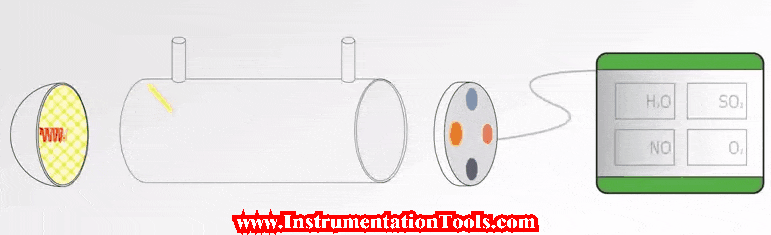
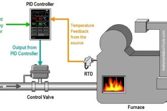
For NDIR Gas analyzer, the main components are an infrared source (lamp), a sample chamber or light tube, a wavelength filter, and the infrared detector. The gas is pumped (or diffuses) into the sample chamber, and gas concentration is measured electro-optically by its absorption of a specific wavelength in the infrared (IR). The IR light is directed through the sample chamber towards the detector.

The detector has an optical filter in front of it that eliminates all light except the wavelength that the selected gas molecules can absorb. Ideally other gas molecules do not absorb light at this wavelength, and do not affect the amount of light reaching the detector. The detector measures the attenuated signal depending amount of gas absorption and it is proportional to the measured gas concentration.

Also Read: Infrared Non Dispersive CO2 Analyzer Working Principle

Don't Miss Our Updates
Be the first to get exclusive content straight to your email.
We promise not to spam you. You can unsubscribe at any time.
Invalid email address
You've successfully subscribed !

Continue Reading

Four Way Solenoid Valve Working Principle
How Modbus is used in Industrial Networks?
Thermal Mass Flow Meter – Principle, Advantages, Applications
Gas Analyzers Interview Questions and Answers
Deluge Valve Working Principle
pH measurement
Share This Article
Facebook Whatsapp Whatsapp LinkedIn Copy Link
Share
3 Comments
  • amin shakiba says:
    May 2, 2016 at 11:36 am

    thank you

    Reply
  • Neeraj Sharma says:
    May 31, 2016 at 2:51 pm

    Thank You so much sir

    Reply
  • Hezy Ram says:
    September 22, 2021 at 2:28 pm

    how much it cost initially? and what is the cost to operate it (yearly)?

    thanks

    Reply

Leave a Reply Cancel reply

Your email address will not be published. Required fields are marked *

Stay Connected

128.3kFollowersLike
69.1kFollowersFollow
210kSubscribersSubscribe
38kFollowersFollow

Categories

Explore More

Dead Weight Tester Working Animation
Technologies for Oxygen Gas Measurement
Conductivity Analyzer Common Problems and Troubleshooting Tips
Electrical Switches Working Animation
Float Level Switch Working Principle Animation
Level Transmitter Animation
How a 4-20mA Transmitter Works?
Strain Gauge Animation

Keep Learning

what-is-gas-metering-system

What is Gas Metering System?

Industrial Gases

Questions and Answers on Gas

Electrical Circuit Label Schematic

Label the Electrical Circuit Schematic

Solenoid-Valve-Working-Animation

Solenoid Valve Working Animation

How to Calibrate pH Electrode?

How to Calibrate pH Electrode?

Flame Ionization Detector (FID)

Flame Ionization Detector (FID) Principle

Ultrasonic Level Switch Working Animation

Ultrasonic Level Switch Working Principle

Two Wire Sensors Animation

Two Wire Sensor Working Principle and Animation

Learn More

Siemens PLC Force LED

Forcing and Modifying PLC Logic

Helix Bimetallic Thermometer Principle

Helix Bimetallic Thermometer Principle

Control Systems Multiple Choice Questions

Volume Booster Working Principle

Control Valve Volume Booster Working Principle

Foundation Fieldbus Tutorials

Foundation Fieldbus Tutorials

Conditional Jump instruction

Jump Instruction in Siemens Tia Portal

What is Partial Stroke Test

What is Partial Stroke Test?

DP type Flow Transmitter Calibration

DP type Flow Transmitter Preventive Maintenance and Calibration

Menu

  • About
  • Privacy Policy
  • Copyright

Quick Links

  • Learn PLC
  • Helping Hand
  • Part Time Job

YouTube Subscribe

Follow US
All rights reserved. Reproduction in whole or in part without written permission is prohibited.
Welcome Back!

Sign in to your account

Username or Email Address
Password

Lost your password?