Inst ToolsInst ToolsInst Tools
  • Courses
  • Automation
    • PLC
    • Control System
    • Safety System
    • Communication
    • Fire & Gas System
  • Instrumentation
    • Design
    • Pressure
    • Temperature
    • Flow
    • Level
    • Vibration
    • Analyzer
    • Control Valve
    • Switch
    • Calibration
    • Erection & Commissioning
  • Interview
    • Instrumentation
    • Electrical
    • Electronics
    • Practical
  • Q&A
    • Instrumentation
    • Control System
    • Electrical
    • Electronics
    • Analog Electronics
    • Digital Electronics
    • Power Electronics
    • Microprocessor
  • Request
Search
  • Books
  • Software
  • Projects
  • Process
  • Tools
  • Basics
  • Formula
  • Power Plant
  • Root Cause Analysis
  • Electrical Basics
  • Animation
  • Standards
  • 4-20 mA Course
  • Siemens PLC Course
Reading: Infrared Non Dispersive CO2 Analyzer Working Principle
Share
Font ResizerAa
Inst ToolsInst Tools
Font ResizerAa
  • Courses
  • Design
  • PLC
  • Interview
  • Control System
Search
  • Courses
  • Automation
    • PLC
    • Control System
    • Safety System
    • Communication
    • Fire & Gas System
  • Instrumentation
    • Design
    • Pressure
    • Temperature
    • Flow
    • Level
    • Vibration
    • Analyzer
    • Control Valve
    • Switch
    • Calibration
    • Erection & Commissioning
  • Interview
    • Instrumentation
    • Electrical
    • Electronics
    • Practical
  • Q&A
    • Instrumentation
    • Control System
    • Electrical
    • Electronics
    • Analog Electronics
    • Digital Electronics
    • Power Electronics
    • Microprocessor
  • Request
Follow US
All rights reserved. Reproduction in whole or in part without written permission is prohibited.
Inst Tools > Blog > Analyzers > Infrared Non Dispersive CO2 Analyzer Working Principle

Infrared Non Dispersive CO2 Analyzer Working Principle

Last updated: January 1, 2016 4:16 pm
Editorial Staff
Analyzers How It Works
12 Comments
Share
2 Min Read
SHARE

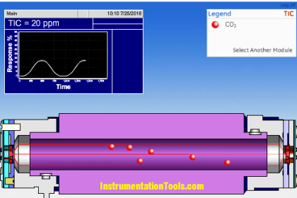
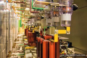
The CO2 Analyser is a Analytical instrument that measures the concentration of CO2 gas in the process. The CO2 Analyzer use multi-component analysis by using Non Dispersive Infrared (NDIR) sensor technology for consistent, precise process gas measurement.

CO2 Analyzer Working Principle

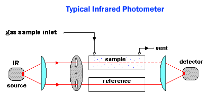
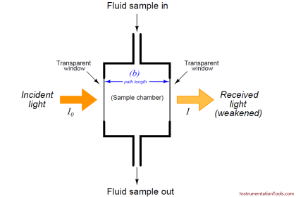
The Non Dispersive Infrared (NDIR) detection method is based upon the absorption of infrared radiation at specific wavelengths as it passes through a volume of sample. Non-Dispersive Infrared (NDIR) techniques for the measurement of various gases rely on the energy absorption characteristics of a particular gas in the infrared region. In a simple NDIR instrument, Infrared energy passes through two identical tubes and falls on a detector. The first tube is the reference cell and is filled with a non-absorbing gas such as nitrogen. The second tube is the measurement cell and contains the gas sample to be analyzed.

CO2 Analzer Working Principle

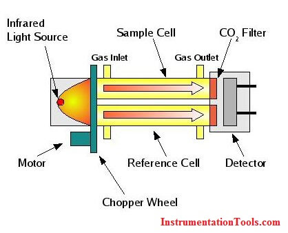
The IR Source continuously sends an IR waves through the gas tubes and detector measures the intensity of two different wavelengths, one at the sample gas absorption wavelength and the other is at reference gas absorption wavelength. As the reference gas generally contains nitrogen so the detector receives 100% signal. If the CO2 gas is present in sample gas means the received signal will be attenuated at the detector side. The detector measures these two signals and their difference is proportional to the amount of absorbing gas in the sample cell .i.e. CO2 gas. So Finally the CO2 gas concentration is measured with the difference in absorption of IR radiation in the sample and reference cells. CO2 gas concentration measuring unit is ppm.

Also See: NDIR Gas Analyzer Animation 

Don't Miss Our Updates
Be the first to get exclusive content straight to your email.
We promise not to spam you. You can unsubscribe at any time.
Invalid email address
You've successfully subscribed !

Continue Reading

Dew Point Meter Principle
Oxygen Analyzer Working Principle
Dead Weight Tester Working Animation
Magnetic Level Indicators Working Animation
Basics of ORP Measurement
Ozone Analyzer Working Principle
Share This Article
Facebook Whatsapp Whatsapp LinkedIn Copy Link
Share
12 Comments
  • Shaju says:
    August 13, 2015 at 7:11 am

    Infrared Non Dispersive ,(NDIR), CO2 gas analyzer working principle is elaborate and informative. Thank you very much.

    Reply
    • S Bharadwaj Reddy says:
      August 13, 2015 at 7:19 am

      Hi Shaju,

      Thanks for the encouraging comments. More will be updated soon. Keep in touch.

      Reply
      • Arsi says:
        January 15, 2016 at 5:08 pm

        Dear sir, i like it for analyzer. Please post all analyzer instruments information.
        thank you

        Reply
  • Jlliot says:
    October 8, 2015 at 10:57 pm

    So many interesting posts i read here on instrumentation, Thank You.

    Reply
  • akash khobragade says:
    May 19, 2016 at 8:39 pm

    This is best in easy way information given by you sir thank you…

    Reply
  • Imteyez says:
    May 30, 2016 at 6:43 pm

    Very good

    Reply
  • Sandeep says:
    July 11, 2016 at 5:17 pm

    it is really very informative, but i want to know more about detector and the chopper used in this type of analyzer.like i read that at detector resonance is created, why? and why is this chopper used in analyzer?

    Reply
    • S Bharadwaj Reddy says:
      July 12, 2016 at 4:02 am

      Hello Sandeep, Chopper is used to split the source for reference cell and sample cell as shown in above figure. Concept is same.

      Reply
      • sandeep says:
        July 12, 2016 at 5:57 am

        Hiii S bharadwaj
        Actually the source is split before chopper as u can see it in the image “Typical infrared Photometer” and in second image also. In this Image chopper is after splitter.

        Reply
  • Rakesh Duvey says:
    July 13, 2016 at 2:03 pm

    Sir pls give me a brief knowledge of stacker Reclaimer and wagon trippler

    Reply
  • Patrick Ndung'u says:
    November 9, 2021 at 4:03 pm

    The information is informative. Thanks a lot

    Reply
  • Jay Wye says:
    September 7, 2022 at 4:45 am

    the chopper is used to modulate the IR signal,not “split” it (or to alternate pulses between sample and reference),so the detectors measure the average of an AC signal. That is for simpler detector amplifiers,less DC drift,more stable calibration. Common in small-signal measurements.

    What I don’t understand is why use two different IR frequencies; surely the different filters would result in different levels of IR at the detectors. the N2 side is not supposed to absorb ANY of the CO2 IR freq,as a 100% reference level,and the sample absorbs some % of the second IR beam,allowing a computation or just subtraction between the 100% and unknown levels,to give the precise amount of absorption. (I’m a former USAF Precision Measurement Equipment tech,aka”PMEL” Calibration is what we do.)
    So I presume the same IR freq is passed through both sample and reference,having the exact same intensity on both sides.

    Reply

Leave a Reply Cancel reply

Your email address will not be published. Required fields are marked *

Stay Connected

128.3kFollowersLike
69.1kFollowersFollow
210kSubscribersSubscribe
38kFollowersFollow

Categories

Explore More

Anti Surge Controller Working Principle
Various Types of Sensors used in Water Treatment Plant
CEMS Principle, Types, Advantages, and Disadvantages
What is Chromatography ?
Sling Psychrometer Principle
Two Electrode Conductivity Probes Principle
Temperature Switch Working Principle
Humidity Measurement Principle

Keep Learning

stepper motors Animation

Fundamentals of DC Motor Animation

Bimetallic strip thermostat

Mechanical Temperature Measuring Sensors

Displacer Operated Level Switch Working Principle

Displacer Level Switch Working Principle

hall-effect-sensor

Hall Effect Sensor Working Principle Animation

Paddle Wheel Flow Meter

Paddle Wheel Flow Meters – Principle, Advantages, Limitations

Impeller Flow Sensor

Impeller Flow Sensor Working Principle and Animation

absorption-type optical analyzer

Absorption Type Optical Analyzer

dissolved-oxygen-probe-calibration-procedure

Dissolved oxygen probe calibration procedure

Learn More

Typical Purging Installation

Purging of Instruments

Relief Valve

Pressure Relief Valve Principle

Single Phase Induction Motors Questions and Answers

Single Phase Induction Motors Questions and Answers

Spiral bimetallic thermometer principle

Spiral Bimetallic Thermometer Principle

Emergency Shutdown Button Installation (ESD)

Understanding Emergency Shutdown Button Installation (ESD)

Programmable Logic Controller (PLC) Questions and Answers

Programmable Logic Controller (PLC) Questions and Answers – 4

PLC Program Upload

How to Upload Siemens PLC Programs?

PLC Handbook

PLC Handbook

Menu

  • About
  • Privacy Policy
  • Copyright

Quick Links

  • Learn PLC
  • Helping Hand
  • Part Time Job

YouTube Subscribe

Follow US
All rights reserved. Reproduction in whole or in part without written permission is prohibited.
Welcome Back!

Sign in to your account

Username or Email Address
Password

Lost your password?