Potentiometric pH measurement
Color-change is a common pH test method used for manual laboratory analyses, but it is not well suited to continuous process measurement. By far the most common pH measurement method in use is electrochemical : special pH-sensitive electrodes inserted into an aqueous solution will generate a voltage dependent upon the pH value of that solution.
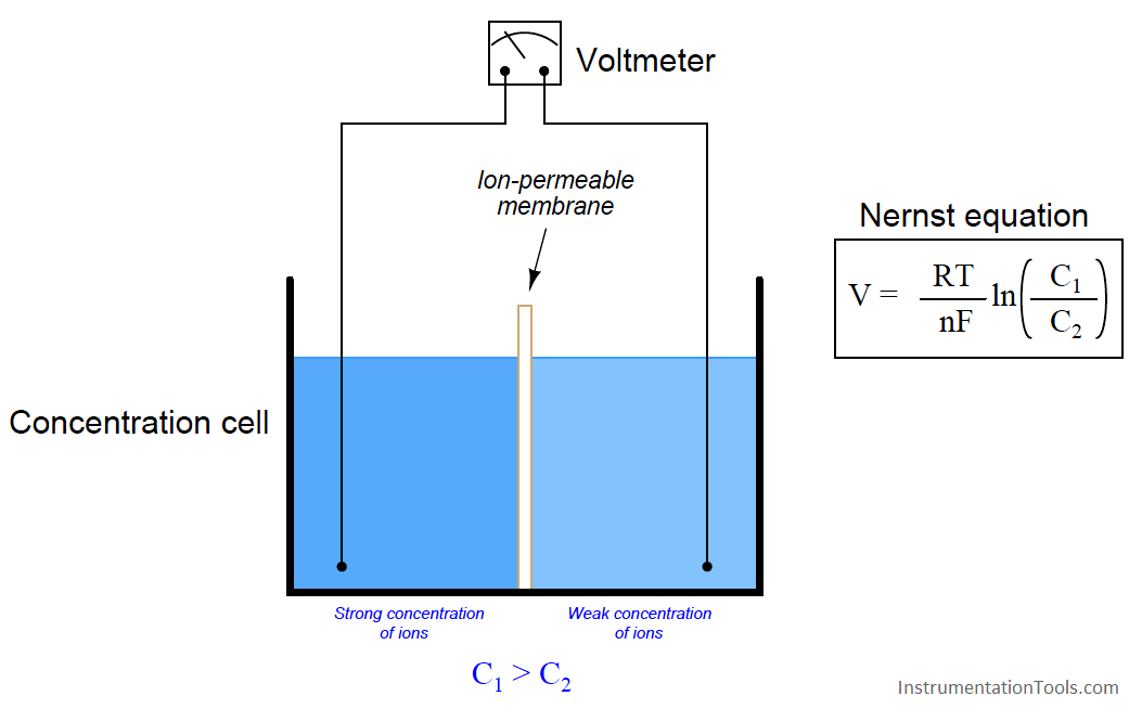
Like all other potentiometric (voltage-based) analytical measurements, electrochemical pH measurement is based on the Nernst equation, which describes the electrical potential created by ions migrating through a permeable membrane. The “textbook example” of this is a device called a concentration cell, where two halves of an electrochemical cell are filled with solutions having different concentrations of ions (i.e. different molarities):
Where,
V = Voltage produced across membrane due to ion exchange (volts)
R = Universal gas constant (8.315 J/mol·K)
T = Absolute temperature (Kelvin)
n = Number of electrons transferred per ion exchanged (unitless)
F = Faraday constant, in coulombs per mole (96485 C/mol e−)
C1 = Concentration of ion in measured solution (moles per liter of solution, M)
C2 = Concentration of ion in reference solution (moles per liter of solution, M)
As ions naturally migrate through this membrane in an attempt to equalize the two concentrations, a voltage corresponding to the difference in ion concentrations between the two cell halves will develop between the two electrodes. The greater the difference in concentrations between the two sides, the greater the voltage produced by the cell. The Nernst voltage may be used to infer the concentration of a specific type of ion if the membrane is selectively permeable to that one type of ion.
We may write the Nernst equation using either natural logarithms (ln) or common logarithms (log). Either form of the Nernst equation works to predict the voltage generated by a concentration cell. The typical form applied to pH measurement calculations is the common log version, which makes more intuitive sense since pH is defined as the common logarithm of hydrogen ion activity:
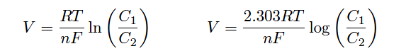
Both forms of the Nernst equation predict a greater voltage developed across the thickness of a membrane as the concentrations on either side of the membrane differ to a greater degree. If the ionic concentration on both sides of the membrane are equal, no Nernst potential will develop.
In the case of pH measurement, the Nernst equation describes the amount of electrical voltage developed across a special glass membrane due to hydrogen ion exchange between the process liquid solution and a buffer solution inside the bulb formulated to maintain a constant pH value of 7.0 pH. Special pH-measurement electrodes are manufactured with a closed end made of this glass, a small quantity of buffer solution contained within the glass bulb:
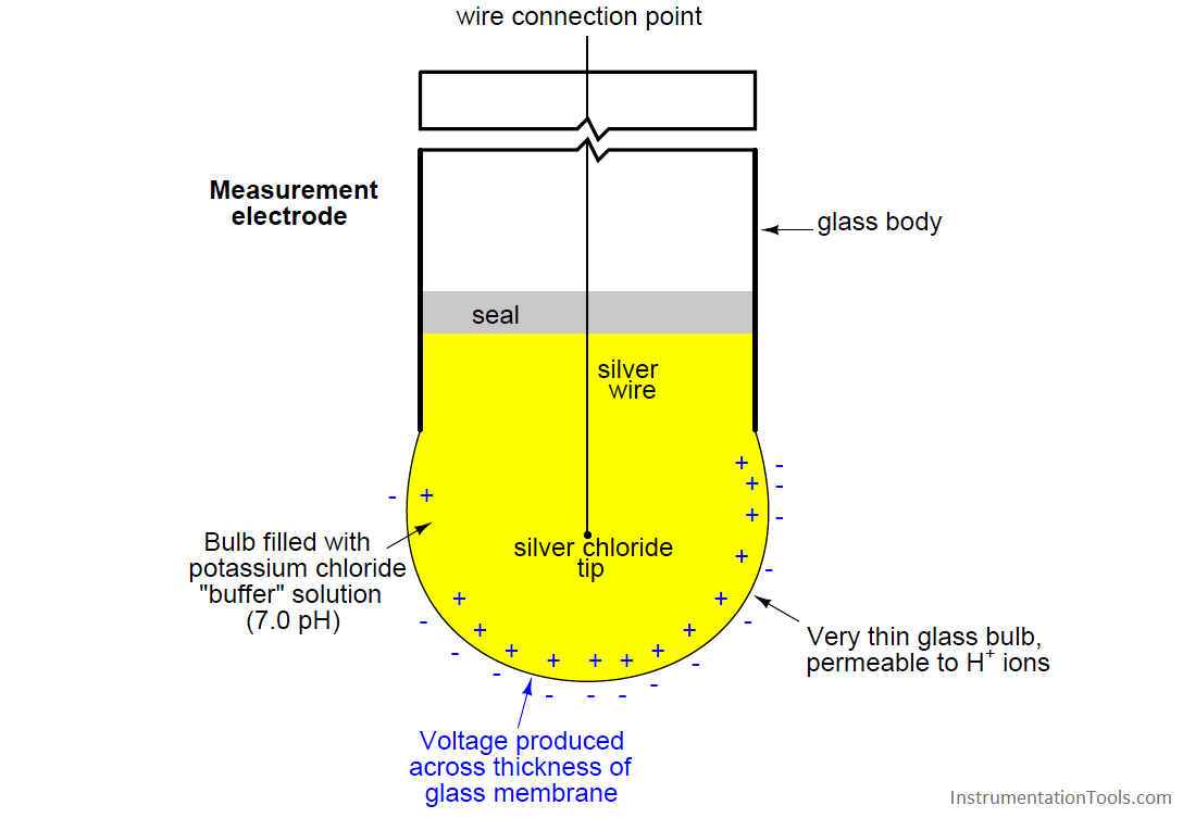
Any concentration of hydrogen ions in the process solution differing from the hydrogen ion concentration in the buffer solution ([H+] = 1 × 10⁻⁷ M) will cause a voltage to develop across the thickness of the glass. Thus, a standard pH measurement electrode produces no potential when the process solution’s pH value is exactly 7.0 pH (i.e. when the process solution has the same hydrogen ion activity as the buffer solution within the bulb).
Given the knowledge that the measurement bulb is filled with a buffer solution having a pH value of 7, we may conclude that one of the concentrations for the glass membrane will always have a value of 1 × 10⁻⁷ M. We may manipulate the Nernst equation to reflect this knowledge, and to express the potential developed in terms of the pH of both solutions, since we know pH is defined the negative logarithm of hydrogen ion molarity:
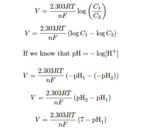
Thus, the Nernst voltage produced by a glass pH electrode is directly proportional to the difference in pH value between the measured solution (pH1) and the probe’s internal 7.0 pH buffer.
The glass used to manufacture this electrode is no ordinary glass. Rather, it is specially manufactured to be selectively permeable to hydrogen ions. If it were not for this fact, the electrode might generate voltage as it contacted any number of different ions in the solution. This would make the electrode non-specific, and therefore useless for pH measurement.
Manufacturing processes for pH-sensitive glass are highly guarded trade secrets. There seems to be something of an art to the manufacture of an accurate, reliable, and long-lived pH electrode. A variety of different measurement electrode designs exist for different process applications, including high pressure and high temperature services.
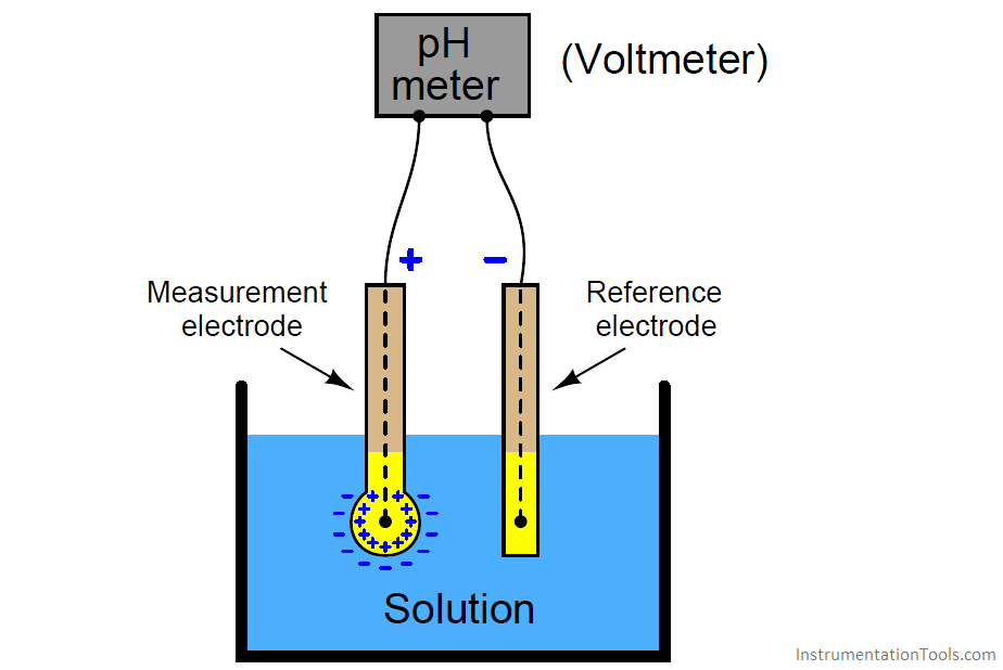
Actually measuring the voltage developed across the thickness of the glass electrode wall, however, presents a bit of a problem: while we have a convenient electrical connection to the solution inside the glass bulb, we do not have any place to connect the other terminal of a sensitive voltmeter to the solution outside the bulb. In order to establish a complete circuit from the glass membrane to the voltmeter, we must create a zero-potential electrical junction with the process solution. To do this, we use another special electrode called a reference electrode immersed in the same liquid solution as the measurement electrode:
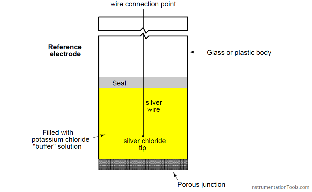
Together, the measurement and reference electrodes provide a voltage-generating element sensitive to the pH value of whatever solution they are submerged in:
The most common configuration for modern pH probe sets is what is called a combination electrode, which combines both the glass measurement electrode and the porous reference electrode in a single unit. This photograph shows a typical industrial combination pH electrode:
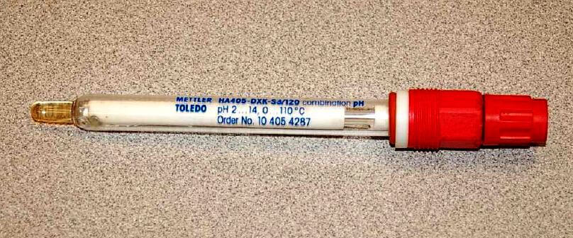
The red-colored plastic cap on the right-hand end of this combination electrode covers and protects a gold-plated coaxial electrical connector, to which the voltage-sensitive pH indicator (or transmitter) attaches.
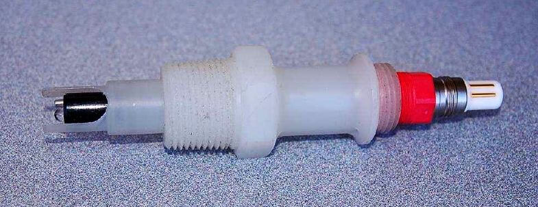
Another model of pH probe appears in the next photograph. Here, there is no protective plastic cap covering the probe connector, allowing a view of the gold-plated connector bars:
A close-up photograph of the probe tip reveals the glass measurement bulb, a weep hole for process liquid to enter the reference electrode assembly (internal to the white plastic probe body), and a metal solution ground electrode:
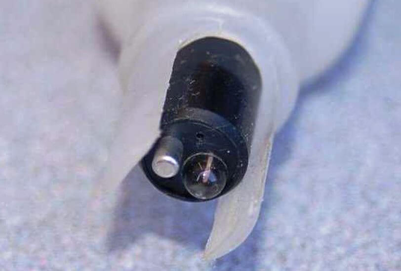
It is extremely important to always keep the glass electrode wet. Its proper operation depends on complete hydration of the glass, which allows hydrogen ions to penetrate the glass and develop the Nernst potential. The probes shown in these photographs are shown in a dry state only because they have already exhausted their useful lives and cannot be damaged any further by dehydration.
The process of hydration – so essential to the working of the glass electrode – is also a mechanism of wear for pH probes. Layers of glass “slough” off over time when continuously hydrated, which means that glass pH electrodes have a limited life whether they are being used to measure the pH of a process solution (continuously wet) or if they are being stored on a shelf (maintained in a wet state by a small quantity of potassium hydroxide held close to the glass probe by a liquid-tight cap). It is therefore impossible to extend the shelf life of a glass pH electrode indefinitely.
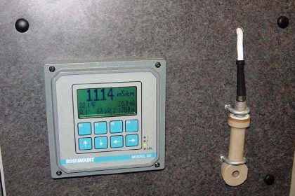
A common installation for industrial pH probe assemblies is to simply dip them into an open vessel containing the solution of interest. This arrangement is very common in water treatment applications, where the water mostly flows in open vessels by gravity at the treatment facility. A photograph showing a pH measurement system for the “outfall” flow of water from an industrial facility appears here:
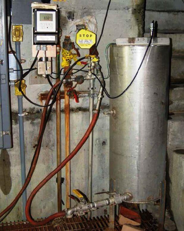
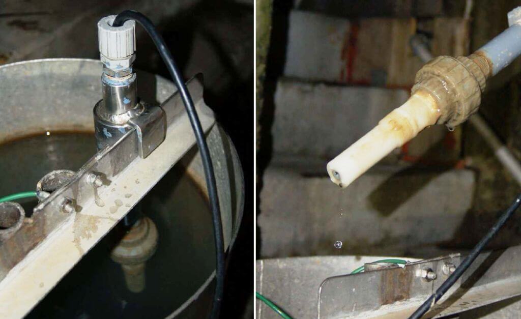
Water flowing from the discharge pipe of the facility enters an open-top stainless steel tank where the pH probe hangs from a bracket. An overflow pipe maintains a maximum water level in the tank as water continuously enters it from the discharge pipe. The probe assembly may be easily removed for maintenance:
An alternative design for industrial pH probes is the insertion style, designed to install in a pressurized pipe. Insertion probes are designed to be removed while the process line remains pressurized, to facilitate maintenance without interrupting continuous operation:
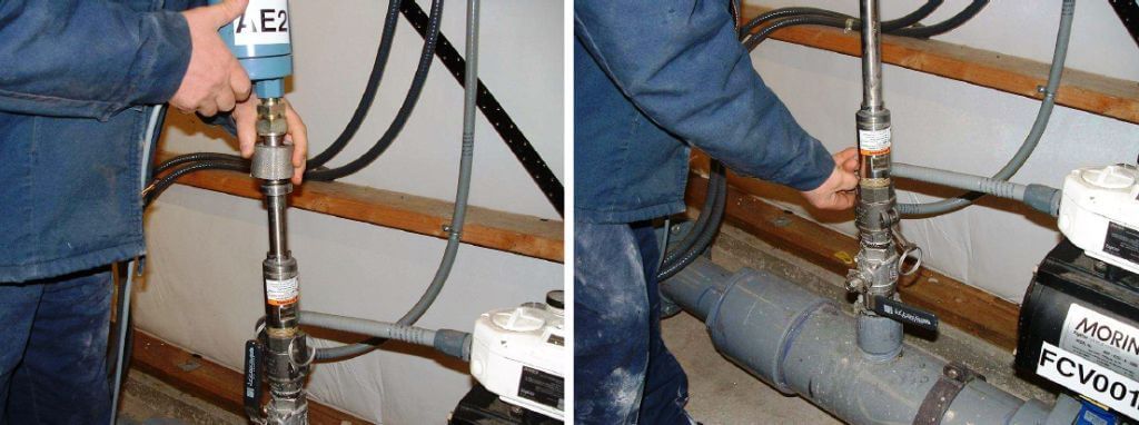
The probe assembly inserts into the process line through the open bore of a 90o turn ball valve. The left-hand photograph (above) shows the retaining nut loosened, allowing the probe to slide up and out of the pipe. The right-hand photograph shows the ball valve shut to block process liquid pressure from escaping, while the technician unlatches the clamps securing the probe to the pipe fitting.
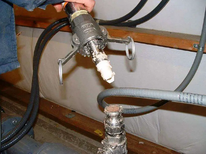
Once the clamp is unlatched, the probe assembly may be completely detached from the pipe, allowing cleaning, inspection, calibration, repair, and/or replacement:
The voltage produced by the measurement electrode (glass membrane) is quite modest. A calculation for voltage produced by a measurement electrode immersed in a 6.0 pH solution shows this. First, we must calculate hydrogen ion concentration (activity) for a 6.0 pH solution, based on the definition of pH being the negative logarithm of hydrogen ion molarity:
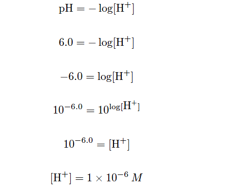
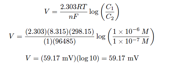
This tells us the concentration of hydrogen ions in the 6.0 pH solution. We know that the buffer solution inside the glass measurement bulb has a stable value of 7.0 pH (hydrogen ion concentration of 1×10⁻⁷M, or 0.0000001 moles per liter), so all we need to do now is insert these values into the Nernst equation to see how much voltage the glass electrode should generate. Assuming a solution temperature of 25 oC (298.15 K), and knowing that n in the Nernst equation will be equal to 1 (since each hydrogen ion has a single-value electrical charge):
We get the same result using our modified version of the Nernst equation:
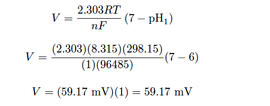
If the measured solution had a value of 7.0 pH instead of 6.0 pH, there would be no voltage generated across the glass membrane since the two solutions’ hydrogen ion activities would be equal. Having a solution with one decade (ten times more: exactly one “order of magnitude”) greater hydrogen ions activity than the internal buffer solution produces 59.17 millivolts at 25 degrees Celsius. If the pH were to drop to 5.0 (two units away from 7.0 instead of one unit), the output voltage would be double: 118.3 millivolts. If the solution’s pH value were more alkaline than the internal buffer (for example, 8.0 pH), the voltage generated at the glass bulb would be the opposite polarity (e.g. 8.0 pH = −59.17 mV ; 9.0 pH = −118.3 mV, etc.).
The following table shows the relationship between hydrogen ion activity, pH value, and probe voltage:
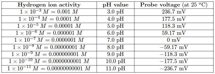
This numerical progression is reminiscent of the Richter scale used to measure earthquake magnitudes, where each ten-fold (decade) multiplication of power is represented by one more increment on the scale (e.g. a 6.0 Richter earthquake is ten times more powerful than a 5.0 Richter earthquake). The logarithmic nature of the Nernst equation means that pH probes – and in fact all potentiometric sensors based on the same dynamic of voltage produced by ion exchange across a membrane – have astounding rangeability: they are capable of representing a wide range of conditions with a modest signal voltage span.
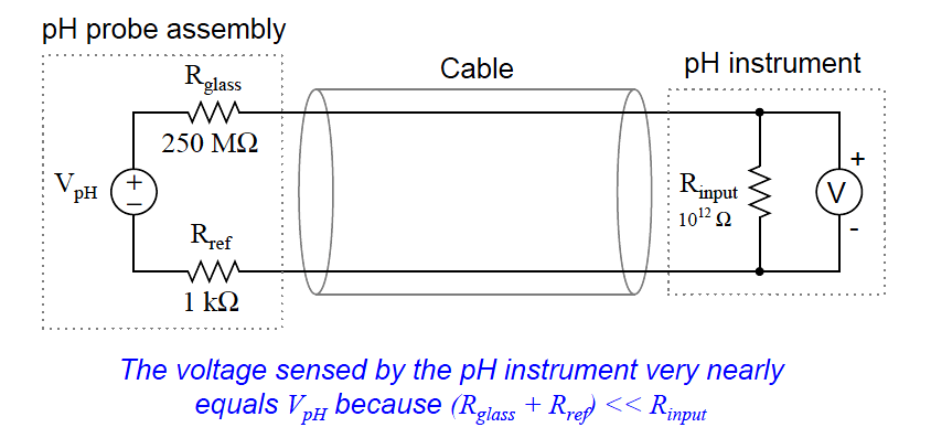
Of course, the disadvantage of high rangeability is the potential for large pH measurement errors if the voltage detection within the pH instrument is even just a little bit inaccurate. The problem is made even worse by the fact that the voltage measurement circuit has an extremely high impedance due to the presence of the glass membrane. The pH instrument measuring the voltage produced by a pH probe assembly must have an input impedance that is orders of magnitude greater yet, or else the probe’s voltage signal will become “loaded down” by the voltmeter and not register accurately.
Fortunately, modern operational amplifier circuits with field-effect transistor input stages are sufficient for this task:
Equivalent electrical circuit of a pH probe and instrument
Even if we use a high-input-impedance pH instrument to sense the voltage output by the pH probe assembly, we may still encounter a problem created by the impedance of the glass electrode: an RC time constant created by the parasitic capacitance of the probe cable connecting the electrodes to the sensing instrument. The longer this cable is, the worse the problem becomes due to increased capacitance:
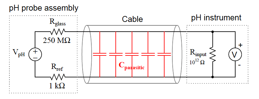
This time constant value may be significant if the cable is long and/or the probe resistance is abnormally large. Assuming a combined (measurement and reference) electrode resistance of 700 M and a 30 foot length of RG-58U coaxial cable (at 28.5 pF capacitance per foot), the time constant will be:
τ = RC
τ = (700 × 106 Ω) (28.5 × 10⁻¹² F/ft)(30 ft))
τ = (700 × 106 )(8.55 × 10⁻¹⁰ F)
τ = 0.599 seconds
Considering the simple approximation of 5 time constants being the time necessary for a first order system such as this to achieve within 1% of its final value after a step-change, this means a sudden change in voltage at the pH probe caused by a sudden change in pH will not be fully registered by the pH instrument until almost 3 seconds after the event has passed!
It may seem impossible for a cable with capacitance measured in picofarads to generate a time constant easily within the range of human perception, but it is indeed reasonable when you consider the exceptionally large resistance value of a glass pH measurement electrode. For this reason, and also for the purpose of limiting the reception of external electrical “noise,” it is best to keep the cable length between pH probe and instrument as short as possible.
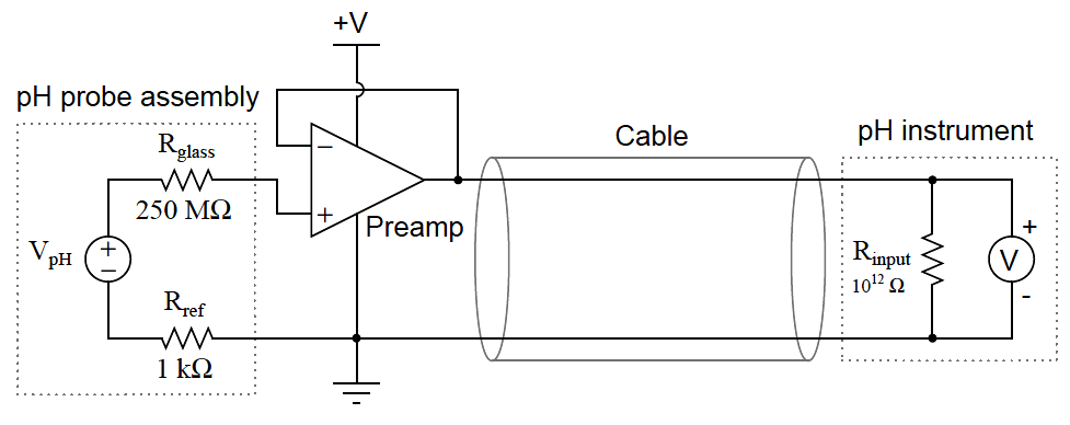
When short cable lengths are simply not practical, a preamplifier module may be connected between the pH probe assembly and the pH instrument. Such a device is essentially a unity-gain (gain = 1) amplifier designed to “repeat” the weak voltage output of the pH probe assembly in a much stronger (i.e. lower-impedance) form so the effects of cable capacitance will not be as severe. A unity-gain operational amplifier “voltage buffer” circuit illustrates the concept of a preamplifier:
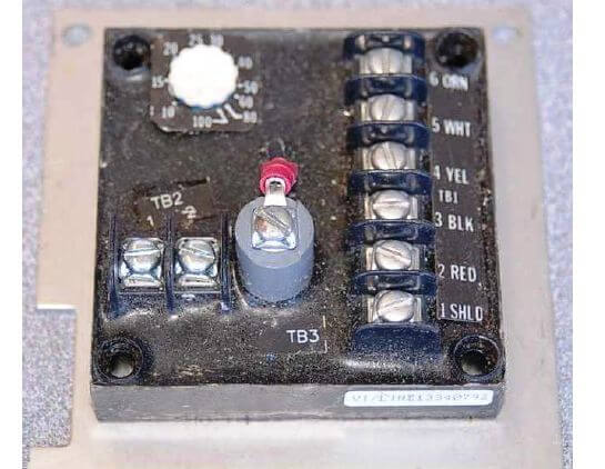
A preamplifier module appears in this next photograph:
The preamplifier does not boost the probes’ voltage output at all. Rather, it serves to decrease the impedance (the Thevenin equivalent resistance) of the probes by providing a low-resistance (relatively high-current capacity) voltage output to drive the cable and pH instrument. By providing a voltage gain of 1, and a very large current gain, the preamplifier practically eliminates RC time constant problems caused by cable capacitance, and also helps reduce the effect of induced electrical noise. As a consequence, the practical cable length limit is extended by orders of magnitude.
Some pH probe assemblies have built-in preamplifier circuits to boost the current-sourcing ability of the probe, rather than relying on a separate preamplifier module connected between the probe and pH instrument. Preamplified pH probes have multi-conductor cables with extra wires used to conduct DC power from the pH transmitter to the pH probe to power the preamplifier:
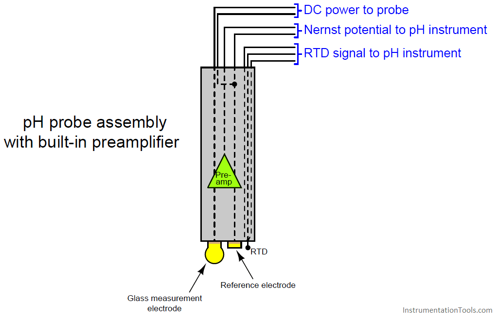
A feature seen in the above amplified probe is an RTD sensor for detecting the temperature of the liquid process solution. This is important because the Nernst equation contains a term for membrane temperature, which means the Nernst potential depends just as much on temperature as it does on ionic concentration. The calculations we performed earlier predicting the amount of voltage produced by different solution pH values all assumed the same temperature: 25 degrees Celsius (298.15 Kelvin). If the solution is not at room temperature, however, the voltage output by the pH probe will not be 59.17 millivolts per pH unit. For example, if a glass measurement electrode is immersed in a solution having a pH value of 6.0 pH at 70 degrees Celsius (343.15 Kelvin), the voltage generated by that glass membrane will be 68.11 mV rather than 59.17 mV as it would be at 25 degrees Celsius. That is to say, the slope of the pH-to-voltage function will be 68.11 millivolts per pH unit rather than 59.17 millivolts per pH unit as it was at room temperature.
The portion of the Nernst equation to the left of the logarithm function defines this slope value:
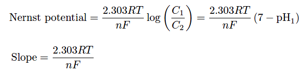
Recall that R and F are fundamental constants, and n is fixed at a value of 1 for pH measurement (since there is exactly one electron exchanged for every H+ ion migrating through the membrane). This leaves temperature (T) as the only variable capable of influencing the theoretical slope of the function.
In order for a pH instrument to accurately infer a solution’s pH value from the voltage generated by a glass electrode, it must “know” the expected slope of the Nernst equation. Since the only variable in the Nernst equation besides the two ion concentration values (C1 and C2) is temperature (T), a simple temperature measurement will provide the pH instrument the information it needs to function accurately. For this reason, many pH instruments are equipped with RTD inputs for solution temperature sensing, and many pH probe assemblies have built-in RTD temperature sensors ready to sense solution temperature.
While the theoretical slope for a pH instrument depends on no variable but temperature, the actual slope also depends on the condition of the measurement electrode. For this reason, pH instruments need to be calibrated for the probes they connect to.
A pH instrument is generally calibrated by performing a two-point test using buffer solutions as the pH calibration standard. A buffer solution is a specially formulated solution that maintains a stable pH value even under conditions of slight contamination. The pH probe assembly is inserted into a cup containing a buffer solution of known pH value, then the pH instrument is calibrated to that pH value. After establishing the first calibration point, the pH probe is removed from the buffer, rinsed, then placed into another cup containing a second buffer with a different pH value. After another stabilization period, the pH instrument is calibrated to this second pH value.
Only two points are necessary to define a line, so these two buffer measurements are all that is required by a pH instrument to define the linear transfer function relating probe voltage to solution pH:
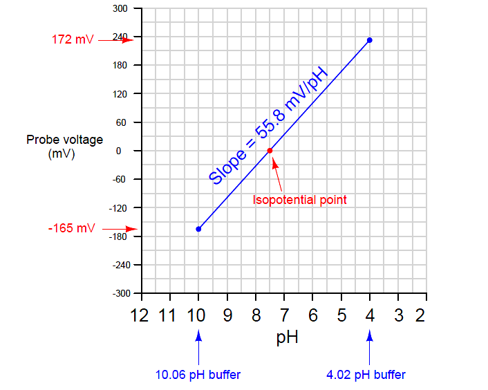
Most modern pH instruments will display the calculated slope value after calibration. This value should (ideally) be 59.17 millivolts per pH unit at 25 degrees Celsius, but it will likely be a bit less than this. The voltage-generating ability of a glass electrode decays with age, so a low slope value may indicate a probe in need of replacement.
Another informative feature of the voltage/pH transfer function graph is the location of the isopotential point: that point on the graph corresponding to zero probe voltage. In theory, this point should correspond to a pH value of 7.0 pH. However, if there exist stray potentials in the pH measurement circuit – for example, voltage differences caused by ion mobility problems in the porous junction of the reference electrode, or contamination of the buffer solution inside the glass electrode bulb – this point will shift. Sufficient contamination of the buffer solution inside the measurement electrode (enough to drive its pH value from 7.0) will also cause an isopotential point shift, since the Nernst equation predicts zero voltage when ion concentrations on both sides of the membrane are equal.
A quick way to check the isopotential point of a pH probe assembly is to short the input terminals on the pH measuring instrument together (forcing Vinput to be equal to 0 millivolts) and note the pH indication on the instrument’s display. This test should be performed after calibrating the instrument using accurate pH buffer solutions. The instrument characterized by the previous graph, for example, will register approximately 7.5 pH with its input terminals shorted because that is the pH value at which its probe happens to output zero millivolts. When calibrating a pH instrument, you should choose buffers that most closely “bracket” the expected range of pH measurement in the process. The most common buffer pH values are 4, 7, and 10. For example, if you expect to measure pH values in the process ranging between 7.5 and 9, for example, you should calibrate that pH instrument using 7 and 10 buffers.
Potentiometric pH probes require regular care and servicing for long life and accurate measurement. For some pH probes, regular service includes refilling a liquid electrolyte reservoir for the reference electrode. Cleaning is a common requirement for pH electrodes in dirty process applications such as wastewater. Both the glass sensing bulb and the reference electrode must have direct contact with the process liquid, with no coating, plugging or other barriers to interfere with ion transfer. If a pH probe is dirty, cleaning should be done with no solid contact made to the glass electrode because the glass electrode is very fragile. Never use a toothbrush, a towel, or any sort of abrasive tool to clean a glass electrode! Liquid probe-cleaning solutions are manufactured to dissolve a number of different types of fouling commonly found on pH probes:
• Fats, greases, and oils – use a non-ionic surfactant or methanol solution
• Proteins – use an acidic pepsin solution
• Minerals – use an acidic solution
• Sulfides – use thiourea solution
• Microbial growth – use thiourea solution
• Salts – use deionized (distilled) water
Pressure-rinsing is a practical technique for cleaning stubborn deposits from pH probes. A hand-pump squirt nozzle using cleaning solution (or in some cases, simply deionized water) is often able to dislodge the matter from a fouled pH probe. Soaking in warm cleaning solution or deionized water is also recommended, especially for dislodging material from the small reference hole (allowing process fluid to reach the reference junction) found in many combination pH probes. Regardless of the cleaning solution used, a thorough rinsing with deionized water is recommended as a final step before returning the pH probe to service.