Inst ToolsInst ToolsInst Tools
  • Courses
  • Automation
    • PLC
    • Control System
    • Safety System
    • Communication
    • Fire & Gas System
  • Instrumentation
    • Design
    • Pressure
    • Temperature
    • Flow
    • Level
    • Vibration
    • Analyzer
    • Control Valve
    • Switch
    • Calibration
    • Erection & Commissioning
  • Interview
    • Instrumentation
    • Electrical
    • Electronics
    • Practical
  • Q&A
    • Instrumentation
    • Control System
    • Electrical
    • Electronics
    • Analog Electronics
    • Digital Electronics
    • Power Electronics
    • Microprocessor
  • Request
Search
  • Books
  • Software
  • Projects
  • Process
  • Tools
  • Basics
  • Formula
  • Power Plant
  • Root Cause Analysis
  • Electrical Basics
  • Animation
  • Standards
  • 4-20 mA Course
  • Siemens PLC Course
Reading: Transistor Failure Rate Calculation
Share
Font ResizerAa
Inst ToolsInst Tools
Font ResizerAa
  • Courses
  • Design
  • PLC
  • Interview
  • Control System
Search
  • Courses
  • Automation
    • PLC
    • Control System
    • Safety System
    • Communication
    • Fire & Gas System
  • Instrumentation
    • Design
    • Pressure
    • Temperature
    • Flow
    • Level
    • Vibration
    • Analyzer
    • Control Valve
    • Switch
    • Calibration
    • Erection & Commissioning
  • Interview
    • Instrumentation
    • Electrical
    • Electronics
    • Practical
  • Q&A
    • Instrumentation
    • Control System
    • Electrical
    • Electronics
    • Analog Electronics
    • Digital Electronics
    • Power Electronics
    • Microprocessor
  • Request
Follow US
All rights reserved. Reproduction in whole or in part without written permission is prohibited.
Inst Tools > Blog > Safety Instrumented System (SIS) > Transistor Failure Rate Calculation

Transistor Failure Rate Calculation

Last updated: March 22, 2019 10:49 am
Editorial Staff
Safety Instrumented System (SIS)
No Comments
Share
2 Min Read
SHARE

Suppose a semiconductor manufacturer creates a microprocessor “chip” containing 2500000 transistors, each of which is virtually identical to the next in terms of ruggedness and exposure to degrading factors such as heat.

The architecture of this microprocessor is such that there is enough redundancy to allow continued operation despite the failure of some of its transistors. This integrated circuit is continuously tested for a period of 1000 days (24000 hours), after which the circuit is examined to count the number of failed transistors.

This testing period is well within the useful life of the microprocessor chip, so we know none of the failures will be due to wear-out, but rather to random causes.

Supposing several tests are run on identical chips, with an average of 3.4 transistors failing per 1000-day test. Calculate the failure rate (λ) and the MTBF for these transistors.

Transistor Failure Rate Calculation

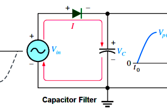
The testing scenario is one where failed components are not replaced, which means both the number of failed transistors and the number of surviving transistors changes over time like voltage and current in an RC charging circuit.

Thus, we must calculate lambda by solving for it in the exponential formula.

Using the appropriate formula, relating number of failed components to the total number of components:

Transistor Failure Rate Calculation

Failure rate may be expressed in units of “per hour,” “Failures In Time” (FIT, which means failures per 109 hours), or “per year” (pa).

MTBF = 1/λ = 1.7647 × 10¹⁰ hours

MTBF = 2.0145 × 10⁶ years

Mean Time Between Failures (MTBF) is essentially the “time constant” for this decaying collection of transistors inside each microprocessor chip.

Articles You May Like :

Single Line Diagram

Logic Gates & Truth tables

Control System Reliability

PLC System Documentation

Torsion Meter Principle

Don't Miss Our Updates
Be the first to get exclusive content straight to your email.
We promise not to spam you. You can unsubscribe at any time.
Invalid email address
You've successfully subscribed !

Continue Reading

SIS Solenoid Valves – Safety PLC
SIS Application Program – Safety Instrumented System
SIS Verification & Validation – Safety Instrumented System
Safety Instrumented System Module Failure
Difference between Availability, Reliability & SIL
What is Partial Stroke Test?
Share This Article
Facebook Whatsapp Whatsapp LinkedIn Copy Link
Share
Leave a Comment

Leave a Reply Cancel reply

Your email address will not be published. Required fields are marked *

Stay Connected

128.3kFollowersLike
69.1kFollowersFollow
210kSubscribersSubscribe
38kFollowersFollow

Categories

Explore More

Over Pressure Protection Devices
Voting Logic in Safety Instrumented System (SIS)
Difference between Process shutdown and Emergency Shutdown
Functional Safety Questions & Answers
SIS Emergency Block Valves (EBV)
SIS Logic Solver
Rupture disks
De-energize to Safe Loop philosophy

Keep Learning

Test Questions on Safety Instrumented System

Test Questions on Safety Instrumented System

HIPPS Operating Philosophy

Understanding High Integrity Pressure Protection Systems (HIPPS)

LAYERS OF PROTECTION ANALYSIS

Layers of Protection Analysis (LOPA) Interview Questions

Parts of Safety PLC

SIS Software Simulation – Safety Instrumented System

Emergency Shutdown Valve

Emergency Shutdown Valve : Advantages

Bathtub curve

Bathtub Curve

pressurized water reactor

SIS Example : Nuclear Reactor Controls

transmitters shared for BPCS and SIS

SIS Instrument Sharing – Transmitters Shared for BPCS and SIS Example

Learn More

Transistor Failure Rate Calculation

Transistor Failure Rate Calculation

Transformer MCQ - Multiple Choice Questions

200+ Transformer MCQ – Multiple Choice Questions

Electrical Machines Questions and Answers

Synchronous Motors Quiz

Difference between Rotary Shaft and Sliding Stem Control Valves

Difference between Rotary Shaft Valves and Sliding Stem Control Valves

Comparison of MOSFET and BJT

Comparison of MOSFET and BJT

PLC Program for Solenoid, Pilot Lamp, and Switch with Alarm

PLC Program for Solenoid, Pilot Lamp, and Switch with Alarm

PLC Program for Password Management using Structured Text

PLC Program for Password Management using Structured Text

DP Diaphragm Capillary Seal Level instrument

DP Diaphragm Capillary Seal Level instrument Calibration Procedure

Menu

  • About
  • Privacy Policy
  • Copyright

Quick Links

  • Learn PLC
  • Helping Hand
  • Part Time Job

YouTube Subscribe

Follow US
All rights reserved. Reproduction in whole or in part without written permission is prohibited.
Welcome Back!

Sign in to your account

Username or Email Address
Password

Lost your password?