Inst ToolsInst ToolsInst Tools
  • Courses
  • Automation
    • PLC
    • Control System
    • Safety System
    • Communication
    • Fire & Gas System
  • Instrumentation
    • Design
    • Pressure
    • Temperature
    • Flow
    • Level
    • Vibration
    • Analyzer
    • Control Valve
    • Switch
    • Calibration
    • Erection & Commissioning
  • Interview
    • Instrumentation
    • Electrical
    • Electronics
    • Practical
  • Q&A
    • Instrumentation
    • Control System
    • Electrical
    • Electronics
    • Analog Electronics
    • Digital Electronics
    • Power Electronics
    • Microprocessor
  • Request
Search
  • Books
  • Software
  • Projects
  • Process
  • Tools
  • Basics
  • Formula
  • Power Plant
  • Root Cause Analysis
  • Electrical Basics
  • Animation
  • Standards
  • 4-20 mA Course
  • Siemens PLC Course
Reading: Multi-mode and Single-mode Optical Fibers
Share
Notification Show More
Font ResizerAa
Inst ToolsInst Tools
Font ResizerAa
  • Courses
  • Design
  • PLC
  • Interview
  • Control System
Search
  • Courses
  • Automation
    • PLC
    • Control System
    • Safety System
    • Communication
    • Fire & Gas System
  • Instrumentation
    • Design
    • Pressure
    • Temperature
    • Flow
    • Level
    • Vibration
    • Analyzer
    • Control Valve
    • Switch
    • Calibration
    • Erection & Commissioning
  • Interview
    • Instrumentation
    • Electrical
    • Electronics
    • Practical
  • Q&A
    • Instrumentation
    • Control System
    • Electrical
    • Electronics
    • Analog Electronics
    • Digital Electronics
    • Power Electronics
    • Microprocessor
  • Request
Follow US
All rights reserved. Reproduction in whole or in part without written permission is prohibited.
Inst Tools > Blog > Communication > Multi-mode and Single-mode Optical Fibers

Multi-mode and Single-mode Optical Fibers

Last updated: July 20, 2018 12:02 pm
Editorial Staff
Communication eBooks
No Comments
Share
5 Min Read
SHARE

In any sort of waveguide – optical, electrical, or even acoustical (sound) – the signal energy may be able to propagate down the waveguide in different orientations. This is true for optical fibers where the core diameter is relatively large compared to the wavelength of the light: there will be many alternative pathways for light to travel along the length of a fiber’s core. Optical fibers with core diameters of 50 microns or more are referred to as multi-mode fibers, because multiple independent pathways, or “modes”, of light are possible within the core’s width.

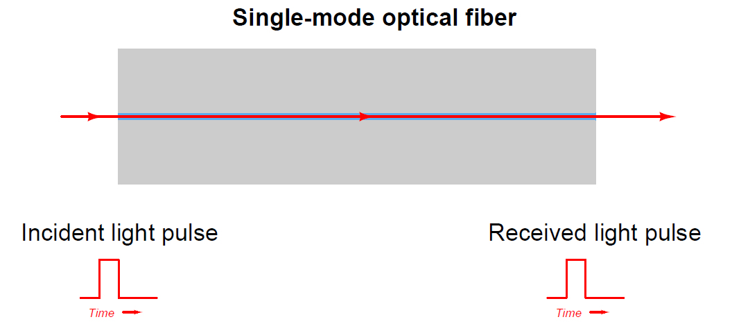
If an optical fiber’s core is manufactured to be small enough, relative to the wavelength of the light used, the fiber will only support one “mode” or pathway down its core. Such fiber is called single-mode. Single-mode fiber cores typically range from 4 to 10 microns in diameter, with 8 micron being typical.

The purpose of single-mode optical fiber is to avoid a problem called modal dispersion. When multiple “modes” of light propagate down the length of an optical fiber, they don’t all have the same length. That is to say, some modes actually take a straighter (and more direct) path down the fiber’s core than others. The reason this is a problem is that this phenomenon corrupts the integrity of high-speed (i.e. short-period) pulses. An exaggerated illustration of this problem appears here, showing the relative path lengths of three different light rays, each one entering the fiber core at a slightly different angle. The light ray closest to parallel with the core’s centerline finds the shortest “mode” to the fiber’s end, and arrives in the least amount of time:

Multi-mode optical fiber

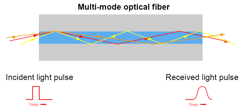
With different “modes” of light arriving at different times from the same incident pulse, the received light pulse at the exiting end of the fiber will no longer possess a crisp “square-wave” shape. Instead, the pulse will be “smeared” over time, occupying a larger time span. This poses a bandwidth limit on the fiber, as there will be some maximum pulse frequency at which adjacent pulses will begin to merge together and become indistinguishable. The longer the length of optical fiber, the more pronounced this dispersion will be. This problem is most evident in applications where the fiber length is very long (hundreds of miles) and the data rate is very high (hundreds of megahertz). Thus, it is a significant problem for long-distance data trunk cables such as those used for transcontinental and intercontinental internet traffic.

Single-mode optical fiber completely averts this problem by eliminating multiple modes within the fiber core. When there is only one mode (pathway) for light to travel, there will be exactly one distance for light to travel from one end of the fiber to the other. Therefore, all portions of the incident light pulse experience the same travel time, and the light pulse arrives at the far end of the cable suffering no modal dispersion:

Single-mode optical fiber

As you can imagine, single-mode fiber is more challenging to splice than multi-mode fiber, as the smaller core diameter provides less room for alignment error.

A compromise solution to the problem of modal dispersion in multi-mode fibers is to manufacture the core glass with a graded index of refraction rather than a homogeneous index of refraction. This means the concentration of doping material in the glass varies from the center of the core to the outer diameter of the core where it interfaces with the cladding. The result of this graded dispersion is that modes traveling closest to the core’s centerline will experience a slower speed of light (i.e. greater index of refraction) than modes near the edge of the core, which means the difference in travel time from one mode to the next will be less pronounced than within normal “step-index” fibers. Of course, this also means graded-index optical fiber is more costly to manufacture than step-index optical fiber.

Don't Miss Our Updates
Be the first to get exclusive content straight to your email.
We promise not to spam you. You can unsubscribe at any time.
Invalid email address
You've successfully subscribed !

Continue Reading

What is Rapid Spanning Tree Protocol? – RSTP Network
Wireless HART Communication Protocol Overview
Fieldbus Control
Different Types of Network Topologies
Comparison between Foundation Fieldbus and Profibus
Things You Need to Know About DeviceNet
Share This Article
Facebook Whatsapp Whatsapp LinkedIn Copy Link
Share
Leave a Comment

Leave a Reply Cancel reply

Your email address will not be published. Required fields are marked *

Stay Connected

128.3kFollowersLike
69.1kFollowersFollow
210kSubscribersSubscribe
38kFollowersFollow

Categories

Explore More

Instrument Tube Bending
OPC Solves Automation’s Data Connectivity
Foundation Fieldbus – Advantages, Limitations, Architecture
Serial Communication Data Transmission Modes
Ultrasonic Level Switch Principle
Foundation Fieldbus Segment Design
What is a Network ?
Difference between HART and Foundation Fieldbus

Keep Learning

Temperature Switch Symbol

Temperature Switch Principle

Difference Between RS232 and RS485

Difference Between RS232 and RS485

Fieldbus Analog Input Function Block

BACNet Protocol

What is the BACNet Protocol? BACNet IP vs. BACNet MS/TP

Difference Between Cyclic and Acyclic Communication

Difference Between Cyclic and Acyclic Communication

What is Timeout in Communication Protocols

What is Timeout in Communication Protocols?

Dissolved oxygen measurement using Optical Fiber Communication

Fiber Optic Sensors

ProfiBus Questions and Answers

Latest ProfiBus Questions and Answers

Learn More

Working of Shuttle valve

What is a Shuttle Valve? Principle, Advantages, Disadvantages

Single-Acting Cylinder Control Operation using Proximity Sensor

Single-Acting Cylinder Control using Proximity Sensor

Yokogawa differential pressure transmitter

Basics of Differential Pressure Transmitters

Ziegler-Nichols closed-loop Tuning - 1

Heuristic PID Tuning Method

What is Gear Run Out

What is Gear Run Out ?

PLC Programming Questions

PLC Programming Question & Answer

RTD-standards

How to calculate the tolerance of a RTD sensor

Abbreviations of Pressure, Temperature & Flow

Abbreviations of Pressure, Temperature & Flow

Menu

  • About
  • Privacy Policy
  • Copyright

Quick Links

  • Learn PLC
  • Helping Hand
  • Part Time Job

YouTube Subscribe

Follow US
All rights reserved. Reproduction in whole or in part without written permission is prohibited.
Welcome Back!

Sign in to your account

Username or Email Address
Password

Lost your password?