Inst ToolsInst ToolsInst Tools
  • Courses
  • Automation
    • PLC
    • Control System
    • Safety System
    • Communication
    • Fire & Gas System
  • Instrumentation
    • Design
    • Pressure
    • Temperature
    • Flow
    • Level
    • Vibration
    • Analyzer
    • Control Valve
    • Switch
    • Calibration
    • Erection & Commissioning
  • Interview
    • Instrumentation
    • Electrical
    • Electronics
    • Practical
  • Q&A
    • Instrumentation
    • Control System
    • Electrical
    • Electronics
    • Analog Electronics
    • Digital Electronics
    • Power Electronics
    • Microprocessor
  • Request
Search
  • Books
  • Software
  • Projects
  • Process
  • Tools
  • Basics
  • Formula
  • Power Plant
  • Root Cause Analysis
  • Electrical Basics
  • Animation
  • Standards
  • 4-20 mA Course
  • Siemens PLC Course
Reading: Thermocouples Green Rot Effect
Share
Notification Show More
Font ResizerAa
Inst ToolsInst Tools
Font ResizerAa
  • Courses
  • Design
  • PLC
  • Interview
  • Control System
Search
  • Courses
  • Automation
    • PLC
    • Control System
    • Safety System
    • Communication
    • Fire & Gas System
  • Instrumentation
    • Design
    • Pressure
    • Temperature
    • Flow
    • Level
    • Vibration
    • Analyzer
    • Control Valve
    • Switch
    • Calibration
    • Erection & Commissioning
  • Interview
    • Instrumentation
    • Electrical
    • Electronics
    • Practical
  • Q&A
    • Instrumentation
    • Control System
    • Electrical
    • Electronics
    • Analog Electronics
    • Digital Electronics
    • Power Electronics
    • Microprocessor
  • Request
Follow US
All rights reserved. Reproduction in whole or in part without written permission is prohibited.
Inst Tools > Blog > Temperature Measurement > Thermocouples Green Rot Effect

Thermocouples Green Rot Effect

Last updated: November 20, 2019 3:27 pm
Editorial Staff
Temperature Measurement
No Comments
Share
5 Min Read
SHARE

Thermocouples Green Rot Effect

Type “K” thermocouples are widely used for temperature measurement and control up to about 2000 Deg F. They operate very well in oxidizing atmospheres.

Contents
Type K ThermocoupleType N Thermocouple

However, if a reducing gas (such as hydrogen) is present, a reducing atmosphere can come in contact with the wires. Under these conditions, with only a very small amount of oxygen present, the chromium in the chromel alloy oxidizes. This reduces the emf output and the thermocouple reads low temperature reading. This phenomenon is known as “green rot,” due to the color of the affected alloy.

Although not always distinctively green, the chromel wire will develop a mottled silvery skin and become magnetic. An easy way to check for this problem is to see if the two wires are magnetic. (Normally, chromel is non-magnetic.)

Hydrogen in the atmosphere is the usual cause of green rot. At high temperatures, it can diffuse through solid metals or an intact metal thermowell. Even the sheath of a magnesium oxide insulated thermocouple will not keep the hydrogen out.

To overcome this problem, a “purged” thermowell is used. Here, a flow of air is brought down through a small tube inside the thermowell to sweep out any hydrogen which has entered the well. (See Below Figure) The small air flow becomes heated on its way down the tube, so it doesn’t chill the sensing junction.

thermocouple installation

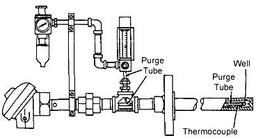
Fig : Installation of a purge tube allows air to be introduced into the thermowell. The air eliminates hydrogen that has entered the well and which would create a reducing atmosphere around the thermocouple.
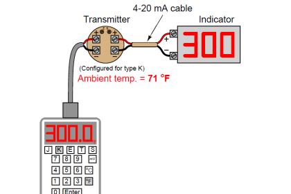
Type K Thermocouple

The Type K thermocouple is composed of a Nickel-10% chromium (+) wire versus a nickel-5% aluminum and silicon (-) wire. This type of thermocouple should only be used in oxidizing or inert atmospheres with a service temperature range between -200°C and 1260°C (-330°F to 2300°F). They are most widely used at temperatures above 540’C (1000″F) due to superior oxidation resistance in comparison to Types E, T, or J.

There are some conditions which should be avoided when using Type K thermocouples. Vacuum applications should not use Type K due to vaporization of chromium in the positive element. Type K thermocouples should not be used in Sulfurous environments since both elements will rapidly corrode and the negative element will eventually fail mechanically due to becoming brittle. Reducing atmospheres should also be avoided.

Low oxygen levels can cause the Green-Rot phenomenon in which the chromium in the elements starts to oxidize causing large negative drifts in calibration. Green-Rot is most pronounced when the thermocouples are used between 815°C to 1040°C (1500°F to 1900°F).

ln order to avoid this problem, large lD protection tubes should be used to maximize internal air circulation or the installation of an oxygen getter in the bottom of the protection tube. lf Green-Rot is a serious problem, Type N thermocouples should be installed.

The negative element, or KN, of a Type K thermocouple can be described by any of the following names: Alumel2, HAI-KN1, ThermoKanthal-KNs, T-2s, Nickel-silicon, or Nial+. The positive element, or KP, of a Type K thermocouple can be described by the following names: Chromel2, Tophel+, ThermoKanthal-KPs, Nickel-chrome, T-13, or HAI-KP1.

Type N Thermocouple

The Type N thermocouple is composed of a nickel-14% chromium-1 1/2% silicon (+) wire versus a nickel 4 1/2% silicon-1/10% magnesium (-) wire. The Type N thermocouple is the newest addition to the ISA family.

lt was developed to be used under the same conditions as a Type K. Type N should be used in oxidizing or inert atmospheres with a service temperature range between -200°C and 1260°C (-330°F to 2300°F).

The addition of silicon and chromium makes this type of thermocouple more resistant to Green-Rot and less drifting when compared to a Type K. The negative element, or NN, of a Type N thermocouple can be described by any of the following names: Nisil, nickel-silicon, or, HAI-NN1. The positive element, or NP, of a Type N thermocouple can be described by any of the following names: Nicrosil, nickel-chromium- silicon, or HAI-NP1 .

Sources : asrichards.com transcat.com

Don't Miss Our Updates
Be the first to get exclusive content straight to your email.
We promise not to spam you. You can unsubscribe at any time.
Invalid email address
You've successfully subscribed !

Continue Reading

Filled-bulb Temperature Sensors
RTD Sensor Connections
Resistance Temperature Detectors (RTD) Construction
Single Position Calibration of Temperature Bath
What is a Thermocouple ?
Optical Pyrometer Working Principle
Share This Article
Facebook Whatsapp Whatsapp LinkedIn Copy Link
Share
Leave a Comment

Leave a Reply Cancel reply

Your email address will not be published. Required fields are marked *

Stay Connected

128.3kFollowersLike
69.1kFollowersFollow
210kSubscribersSubscribe
38kFollowersFollow

Categories

Explore More

Temperature Measurement Interview Questions
Foundation Fieldbus Temperature Transmitter Configuration
Temperature Sensor Accessories
Relationship between Temperature Scales
RTD Calculator Software
Thermocouple Temperature Range Questions and Answers
What is a Temperature Controller? – How to Choose?
RTD Standards

Keep Learning

Thermowell Design Guidelines

Bimetallic strip thermostat

Mechanical Temperature Measuring Sensors

Thermocouple Law of Intermediate Metals

Thermocouples Law of Intermediate Metals

Resistance Temperature Detectors Troubleshooting Tips

Resistance Temperature Detectors Troubleshooting Tips

Van Stone Type Thermowell

Types of Thermowells

testing-thermocouples-and-rtds

Testing thermocouples and RTDs using Multi-function Calibrators

Temperature Switch

Temperature Switch Working Principle

thermocouple voltages

Manually Interpreting Thermocouple Voltages

Learn More

How to Select the Right Encoder for Your Machine

How to Select the Right Encoder for Your Machine?

Boiler Feed Water Treatment

Boiler Feed Water Treatment

Permit to Work System Online Test

Permit to Work System Online Test

Four Wire HART Transmitters

4-wire Passive versus Active Transmitters

control of level in three cascaded Loops

Multiple Lags (orders)

PLC Batch System for 4 Tanks Mixing using CX-Programmer

PLC Batch System for 4 Tanks Mixing using CX-Programmer

Chromatography Questions & Answers

Detection System of Gas Chromatography Questions and Answers

Motor Protection Relay

Motor Protection Circuits

Menu

  • About
  • Privacy Policy
  • Copyright

Quick Links

  • Learn PLC
  • Helping Hand
  • Part Time Job

YouTube Subscribe

Follow US
All rights reserved. Reproduction in whole or in part without written permission is prohibited.
Welcome Back!

Sign in to your account

Username or Email Address
Password

Lost your password?