Inst ToolsInst ToolsInst Tools
  • Courses
  • Automation
    • PLC
    • Control System
    • Safety System
    • Communication
    • Fire & Gas System
  • Instrumentation
    • Design
    • Pressure
    • Temperature
    • Flow
    • Level
    • Vibration
    • Analyzer
    • Control Valve
    • Switch
    • Calibration
    • Erection & Commissioning
  • Interview
    • Instrumentation
    • Electrical
    • Electronics
    • Practical
  • Q&A
    • Instrumentation
    • Control System
    • Electrical
    • Electronics
    • Analog Electronics
    • Digital Electronics
    • Power Electronics
    • Microprocessor
  • Request
Search
  • Books
  • Software
  • Projects
  • Process
  • Tools
  • Basics
  • Formula
  • Power Plant
  • Root Cause Analysis
  • Electrical Basics
  • Animation
  • Standards
  • 4-20 mA Course
  • Siemens PLC Course
Reading: Type E thermocouple Calculations
Share
Font ResizerAa
Inst ToolsInst Tools
Font ResizerAa
  • Courses
  • Design
  • PLC
  • Interview
  • Control System
Search
  • Courses
  • Automation
    • PLC
    • Control System
    • Safety System
    • Communication
    • Fire & Gas System
  • Instrumentation
    • Design
    • Pressure
    • Temperature
    • Flow
    • Level
    • Vibration
    • Analyzer
    • Control Valve
    • Switch
    • Calibration
    • Erection & Commissioning
  • Interview
    • Instrumentation
    • Electrical
    • Electronics
    • Practical
  • Q&A
    • Instrumentation
    • Control System
    • Electrical
    • Electronics
    • Analog Electronics
    • Digital Electronics
    • Power Electronics
    • Microprocessor
  • Request
Follow US
All rights reserved. Reproduction in whole or in part without written permission is prohibited.
Inst Tools > Blog > Practical Questions > Type E thermocouple Calculations

Type E thermocouple Calculations

Last updated: June 6, 2018 9:48 am
Editorial Staff
Practical Questions
No Comments
Share
2 Min Read
SHARE

Type E thermocouple

Calculate the amount of voltage “seen” by the voltmeter given the following measurement and reference junction temperatures:

Type E thermocouple

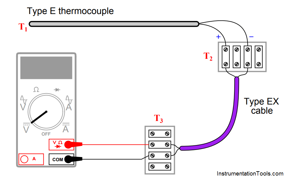
  • T1 = 233 oC ; T2 = 31 oC ; T3 = 25 oC ; Vmeter = __________ mV
  • T1 = 348 oC ; T2 = 40 oC ; T3 = 16 oC ; Vmeter = __________ mV
  • T1 = −161 oC ; T2 = −4 oC ; T3 = 23 oC ; Vmeter = __________ mV
  • T1 = 836 oC ; T2 = 34 oC ; T3 = 19 oC ; Vmeter = __________ mV

Answer :

All answers based on ITS-90 thermocouple table values:

  • T1 = 233 oC ; T2 = 31 oC ; T3 = 25 oC ; Vmeter = 14.395 mV
  • T1 = 348 oC ; T2 = 40 oC ; T3 = 16 oC ; Vmeter = 23.856 mV
  •  T1 = −161 oC ; T2 = −4′oC ; T3 = 23 oC ; Vmeter = −9.039 mV
  • T1 = 836 oC ; T2 = 34 oC ; T3 = 19 oC ; Vmeter = 62.701 mV

Note: all temperatures at T2 are irrelevant because this is a junction between similar metals (type E wires connecting to corresponding type EX extension wires). The reference (cold) junction is where the type EX wires connect to copper, at temperature T3.

Don't Miss Our Updates
Be the first to get exclusive content straight to your email.
We promise not to spam you. You can unsubscribe at any time.
Invalid email address
You've successfully subscribed !

Continue Reading

Solenoid Valves Questions & Answers – 3
pH Monitoring System Triggers an Alarm
Practical Process Control System Questions & Answers – 10
PLC Switch Actuation Status
Calculate Process Temperature using a Thermocouple
What Affect the Pressure Measurement Accuracy of a Manometer?
Share This Article
Facebook Whatsapp Whatsapp LinkedIn Copy Link
Share
Leave a Comment

Leave a Reply Cancel reply

Your email address will not be published. Required fields are marked *

Stay Connected

128.3kFollowersLike
69.1kFollowersFollow
210kSubscribersSubscribe
38kFollowersFollow

Categories

Explore More

PLC Permissive for Motor Control
How Nuclear Radiation is used to Measure Coke Dust Level?
How a Bourdon Tube Pressure Gauge might be Adjusted for Linearity?
Identify High Flow Alarm and Low Flow Alarm?
What is the Purpose of Chemical Seals Pressure Transmitter?
Practical Process Control System Questions & Answers – 12
Calculate Total Hydrostatic Pressure at Bottom of Vessel
Programmable Logic Controller (PLC) Questions and Answers – 3

Keep Learning

Differential Pressure Measurement across Baghouse

Differential Pressure Measurement across Baghouse

A Question on Density Gauge

Air Pressure Regulator cut-away diagram

Air Pressure Regulator Questions

pressure switch control two lamps wiring

Draw Wiring of a Pressure Switch to control two lamps

solenoid valves trip

Identify Solenoid Valves Energized or de-energized?

How Much Pressure indicated by Micromanometer

How Much Pressure Indicated by Micromanometer?

Fisher model 546 I to P transducer

Fisher model 546 I/P transducer

three-phase motor control circuits

How Overload Heaters used to Automatically Shut the Motor OFF ?

Learn More

Practical Process Control System Questions

Process Control Loop Testing

Seven Segment Display Programming with Structured Text

Seven Segment Display Programming with Structured Text

Switch or Transmitter

Switch or Transmitter

How is Electricity Generated From Solar Energy

How is Electricity Generated From Solar Energy?

Top 100 LabVIEW Projects for Engineering Students

Top 100 LabVIEW Projects for Engineering Students

Applications of Tilting Level Switch

How Tilt Level Switch Works ?

Polyphase Induction Motor Multiple Choice Questions and Answers

200+ Polyphase Induction Motor Multiple Choice Questions and Answers

Thermocouple Software compensation

Thermocouple Software compensation

Menu

  • About
  • Privacy Policy
  • Copyright

Quick Links

  • Learn PLC
  • Helping Hand
  • Part Time Job

YouTube Subscribe

Follow US
All rights reserved. Reproduction in whole or in part without written permission is prohibited.
Welcome Back!

Sign in to your account

Username or Email Address
Password

Lost your password?