Many times, we hear the word thermocouple extension cable and thermocouple compensating cable. We get confused because both thermocouple extension cable and thermocouple compensating cable looks similar.
Today we will learn what is the difference between thermocouple extension cable and thermocouple compensating cable.
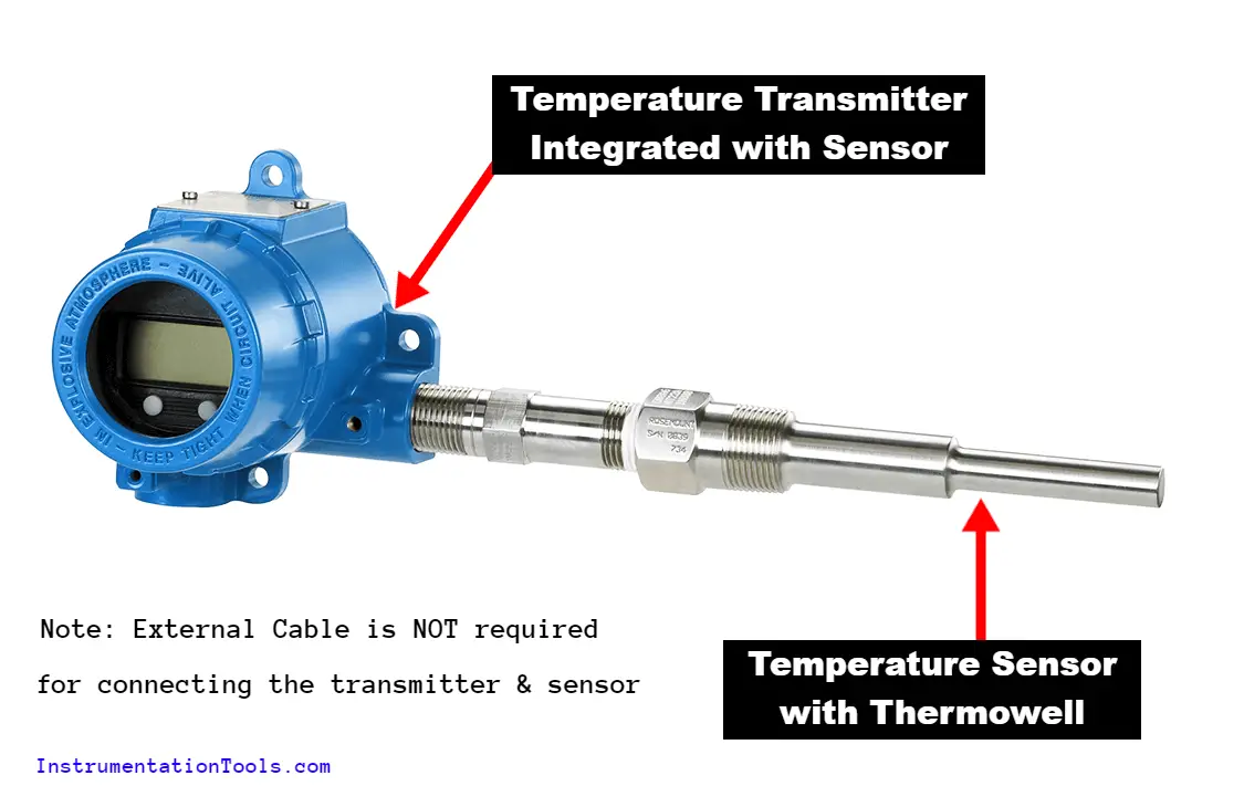
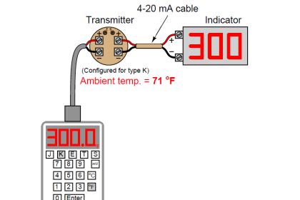
Temperature Transmitter with Integrated Sensor
When the temperature sensor is integrated with the temperature transmitter then there is no requirement for extension or compensating cables as shown in the below figure.
The thermocouple is a primary temperature sensing element. Thermocouple gives output in terms of millivolt as per the measured temperature. The millivolt is given to the temperature transmitter which converts the millivolt signal to a 4 to 20 mA output that will be connected to the control system (PLC/DCS/ESD).
The thermocouple may be installed at a different location and the transmitter may be installed at a different location. We need a cable to connect the thermocouple and temperature transmitter.
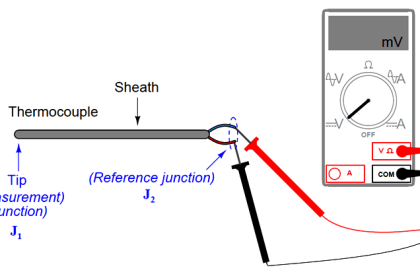
The basic law of thermocouple i.e. Seebeck effect. Seebeck effect says that if two dis-similar are connected at two end points forming two junctions and if both the junctions are kept at different temperatures, then a current will start flowing from the hot junction to the cold junction.
The potential difference generates millivolts which are proportional to the temperature difference between the hot junction and cold junction which is the temperature that is to be measured.
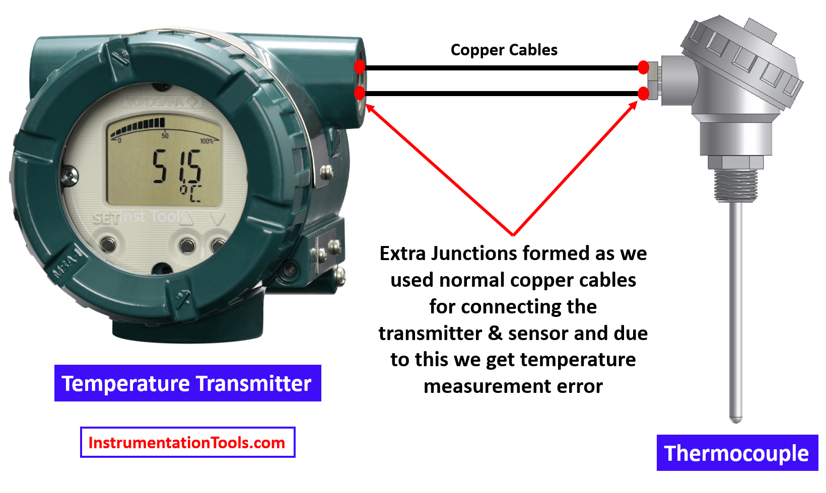
As discussed above, an external cable is used to connect the thermocouple and the temperature transmitter. This extra cable can be made from copper or from the respective thermocouple type material.
So, if we use the extra cable made from copper, then two more junctions will form because the thermocouple material is different from this cable as shown in the above figure. This will affect the generation of milli volts and thus we get the wrong temperature measurement readings.
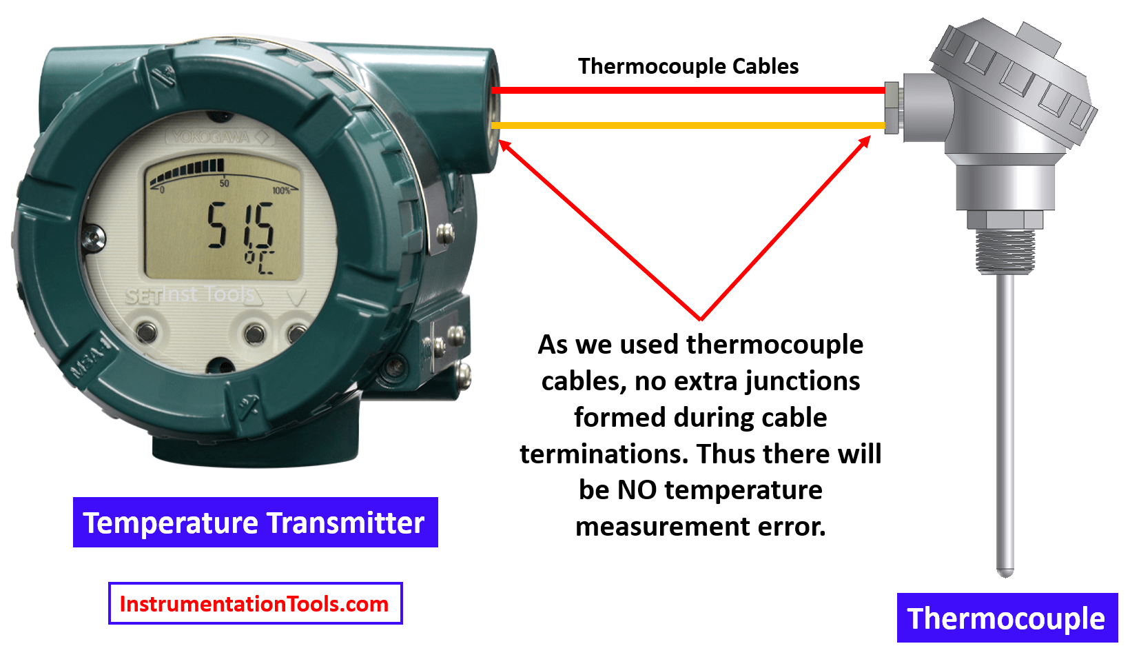
So, in this case, we will require a special type of cable called thermocouple extension cable or thermocouple compensation cable in order to avoid measurement error.
Thermocouple Extension Cable
The thermocouple extension cable is a type of cable which is used to connect the thermocouple to a temperature transmitter that is located at a distance.
The thermocouple extension cables are made up of the same material as that of the main thermocouple leads.
Thermocouple extension cables for K-type of thermocouples are made of chromel and alumel which is the same material used for the construction of K-type thermocouples.
Thermocouple Compensating Cable
A thermocouple Compensating cable is another type of cable used to connect the thermocouple and the temperature transmitter. For thermocouple compensating cable, the cables used are having similar electrical properties to that of thermocouple material.
Because the thermocouple compensating cables are having similar electrical properties to that of thermocouple cable material, the temperature vs voltage output for these thermocouple compensating cables is also the same for a limited range.
We prefer thermocouple compensating cable for thermocouple having cable material made up of precious metals. Thermocouples like B-type thermocouples, R-type thermocouples, and S-type thermocouples have cable material made up of precious materials like Platinum and Rhodium.
For B-type thermocouples, R-type thermocouples, and S-type thermocouples, the cost of extension cables will be very high. For this reason, thermocouple compensating cables are used where we have budget limitations.
If you liked this article, then please subscribe to our YouTube Channel for Electrical, Electronics, Instrumentation, PLC, and SCADA video tutorials.
You can also follow us on Facebook and Twitter to receive daily updates.
Read Next:
- Thermowell Installation
- Temperature Sensors Failure
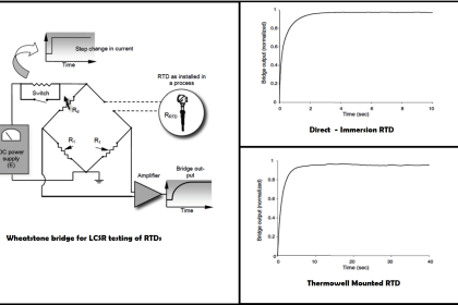
- Response Time Test of RTD
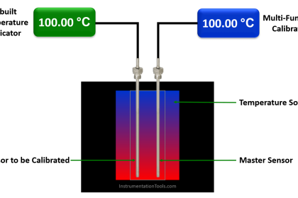
- Temperature Sensor Calibration
- Pneumatic Temperature Sensor


What about thermocouple signals connected directly into the PLC? Can we use the same thermocouple extension cable?