Thermocouple wiring
- The thermocouple extension wire should meet the requirements of ISA/ANSI MC96.1 or IEC-60584.
- Thermocouple signals are low-level signals that should be properly shielded and grounded to prevent noise interference with the signal.
- Insulated hot junctions shall have an insulation resistance to ground of 50 megohms minimum at ambient temperature and 2 megohms minimum at 4508C (8508F).
- Terminals within the head shall be clearly marked ‘+’, ‘-’, ‘ground’, as appropriate.
- The multi circuits within heads shall be clearly identified
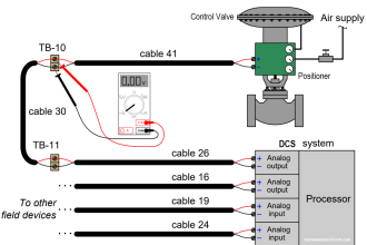
- Check that the polarity and continuity of the lead wires are consistent through all the junction boxes from the thermocouple head to the control center
Grounded Thermocouple
- For grounded thermocouples, check that the shield wire is terminated at the grounded thermocouple head in accordance with the manufacturer’s instructions and not at the shield connection on the control center or instrument terminals
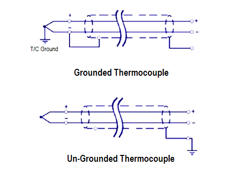
Un-Grounded Thermocouple
- For ungrounded thermocouples, check that the shield wire is terminated in the control room.
- Grounding of the shield at more than one location should be avoided. Individual shielding of multi-pair cables, in addition to an overall shield, can help maintain the shield circuit at the individual ground potential all the way back to the receiver location.
Notes
- Thermocouples can be tested by immersion in a temperature bath and the output measured using a Portable Calibrator.
- Thermocouple selection is done based on temperature range and accuracy as per ISA/ANSI/IEC standards.
Thermocouple Color Codes
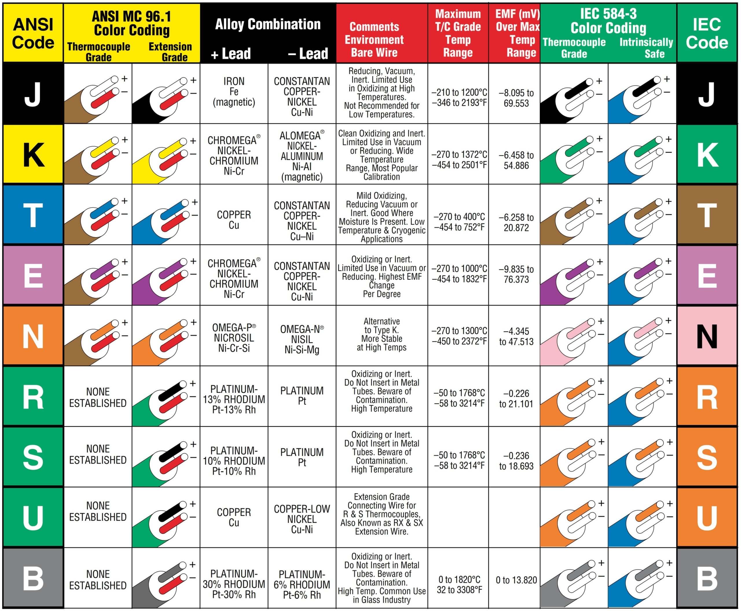
Image Courtesy: Omega
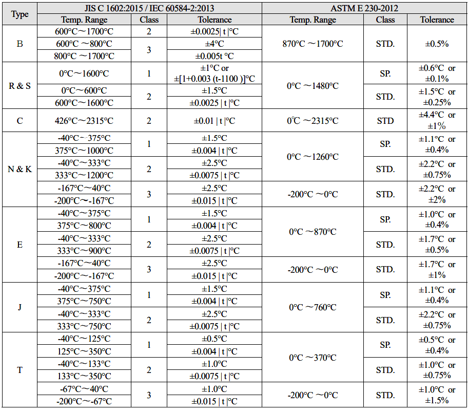
Thermocouple Tolerance
1) Tolerance is referred to as the maximum allowable deviation between hot junction temperature and the temperature derived from the EMF table.
2) ASTM temperature is C or % value for the measured temperature, which is greater.
3) | t | is the measuring temperature indicated by the temperature irrelevant to the symbol + or -.
4) Class 1, 2, or 3 conforms to the old JIS Class 0.4, 0.75 or 1.5, respectively.
5) JIS Standard is identical with IEC, BS or DIN Standard except for a part.
6) The tolerance of JISC1605 and JISC1602 is completely the same.
7) ASTM Standard is same as the old ANSI Standard.
8) Tolerances given in this table apply only to new wire as delivered to the user and do not allow for changes in characteristics with use. (ASTM E230)
9) The standard tolerances shown do not apply to Type E mineral-insulated, metal-sheathed (MIMS) thermocouples and thermocouple cables as described in Specifications E608/E608M and E585/E585M. The standard tolerances for MIMS Type E constructions are the greater of 2.2°C or 0.75 % from 0 to 870°C and the greater of 2.2°C or 2 % from -200 to 0°C.
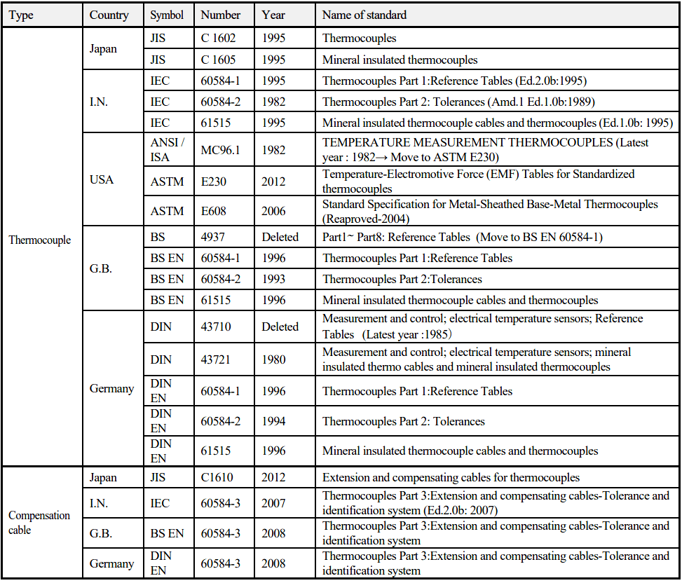
Thermocouple Standard
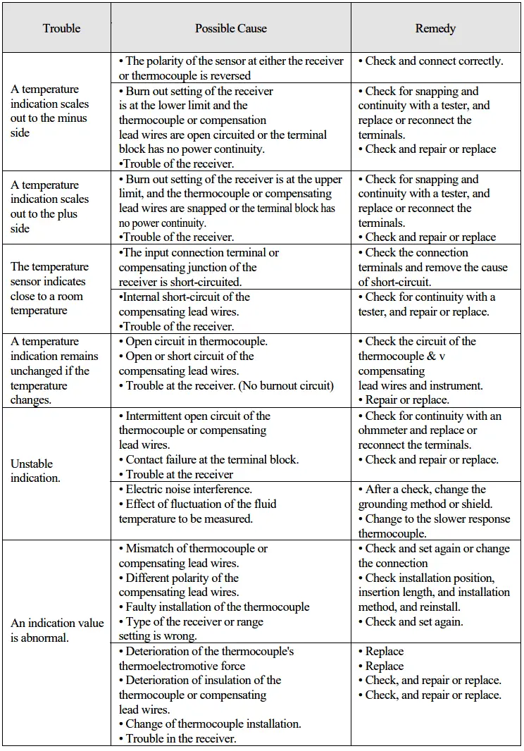
Thermocouple Troubleshooting
Reference: okazaki
Author: Mohammed Khaleel
Read Next:
- RTD Construction
- RTD Temperature Error
- Thermocouple Applications
- Thermocouple Construction
- Terminate the Cable Shield


A very good article, with lot of required information can be found at a place. Inclusion of thermocouple color code chart as per the IEC and ANSI standards may be considered for adding more fragrance to the article.
You may find the following site of interest when dealing with thermowells and temperature response times,
https://www.thermowellsoftware.com